Eureka AIR delivers breakthrough ideas for toughest innovation challenges, trusted by R&D personnel around the world.

Integrated liquid cooling system for electrical components

Inactive Publication Date: 2005-03-17
HON HAI PRECISION IND CO LTD
View PDF11 Cites 14 Cited by
  • Summary
  • Abstract
  • Description
  • Claims
  • Application Information

AI Technical Summary

Benefits of technology

[0007] Accordingly, an object of the present invention is to provide a liquid cooling system which has an enhanced cooling performance.
[0008] Another object of the present invention is to provide a liquid cooling system which can be readily installed or removed to or from an electrical enclosure.

Problems solved by technology

The traditional cooling means such as combined heat sinks and cooling fans are increasingly unable to provide satisfactory cooling performance.
Installation and removal of the cooling system can be troublesome and problematic.
In addition, a large space for these discrete components is required.
Further, the coolant generally can not be completely cooled by passing the heat sink, due to a small contact area between the tube and the heat sink.

Method used


Image

  • Integrated liquid cooling system for electrical components
  • Integrated liquid cooling system for electrical components
  • Integrated liquid cooling system for electrical components

Examples


Embodiment Construction

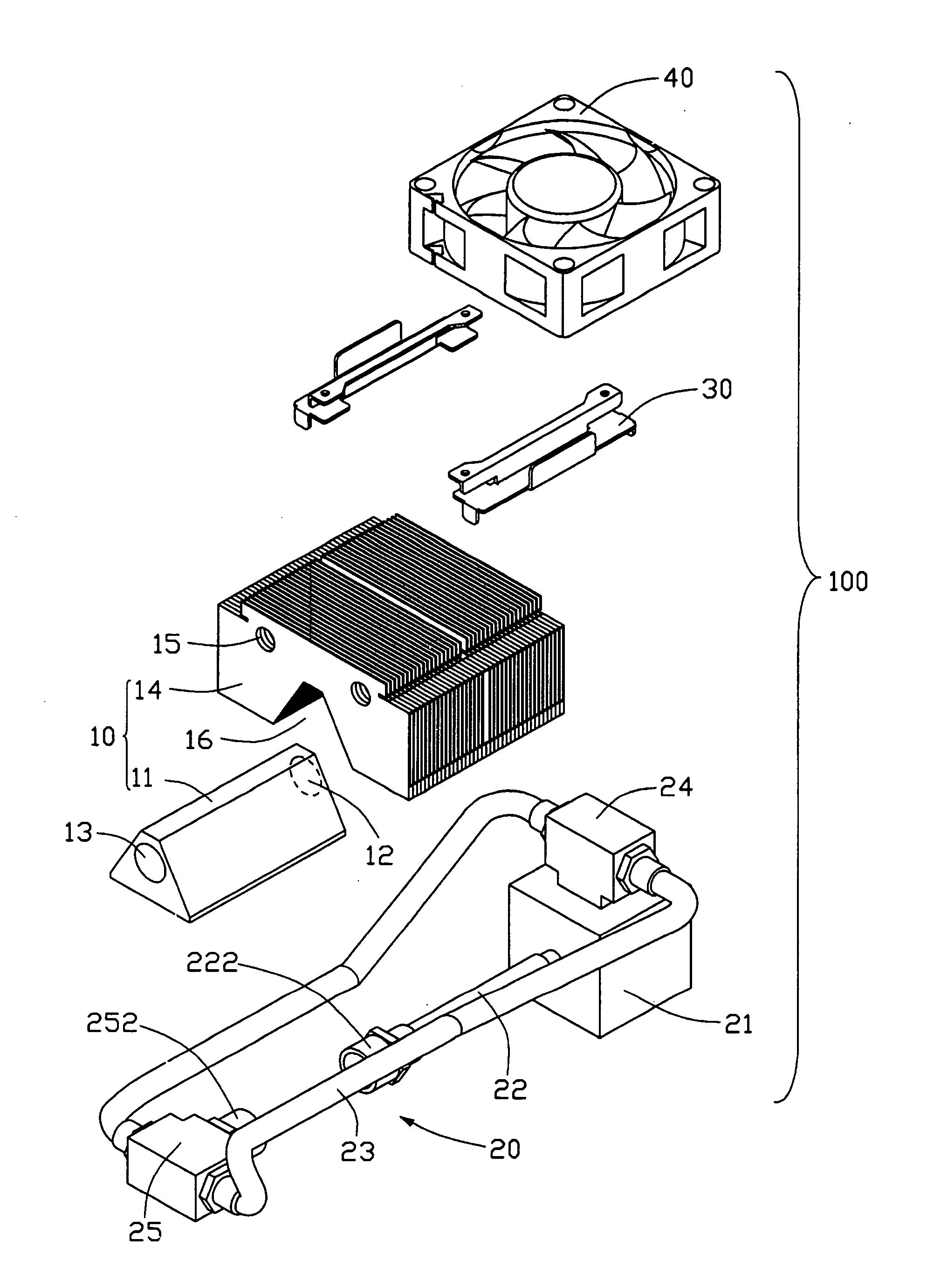
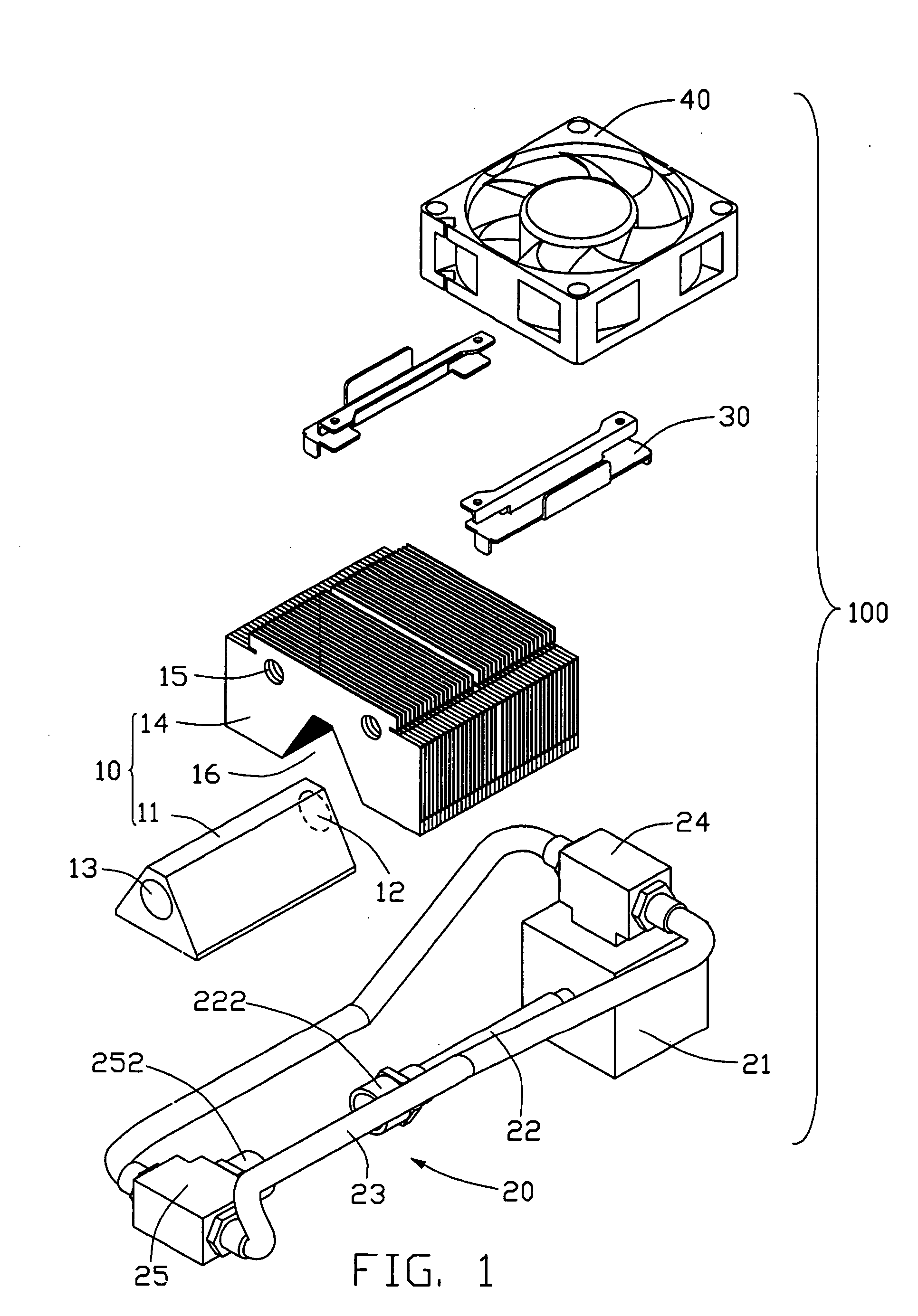
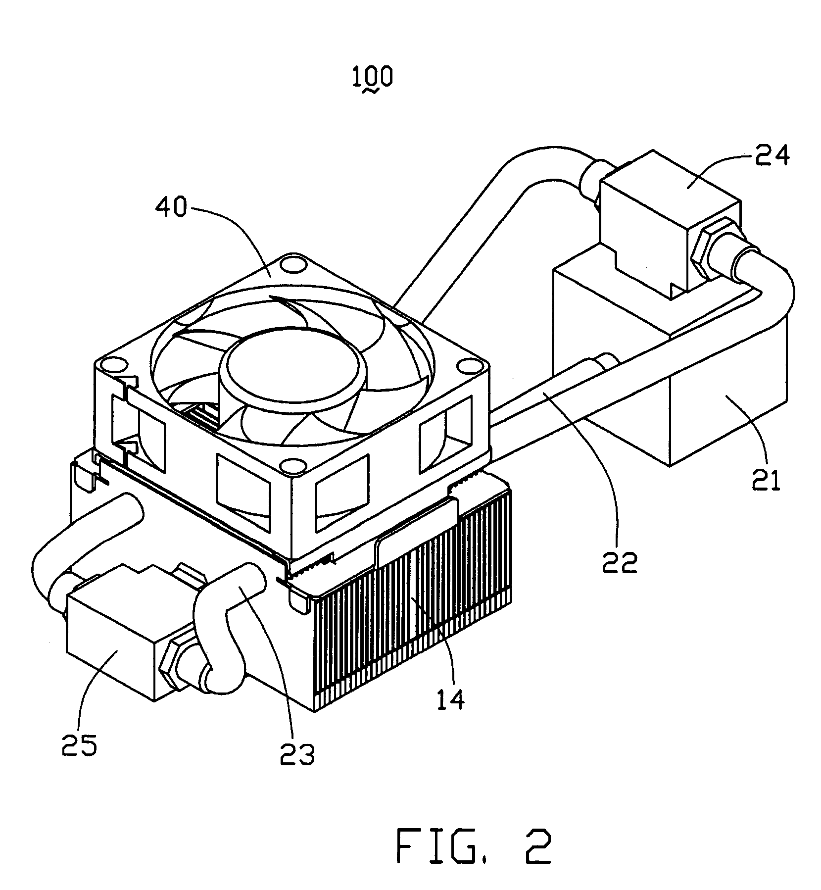
[0013] Referring to FIGS. 1 and 2, a liquid cooling system 100 in accordance with a preferred embodiment of the present invention comprises a cooling body 10, a liquid circulation module 20 coupled to the cooling body 10, and a fan 40 mounted on the cooling body 10.

[0014] The cooling body 10 comprises a cooling base 11 for thermally contacting a heat generating component (not shown), and a heat sink 14 mounted on the cooling base 11. The cooling base 11 has a trapezoid cross section with a top side being smaller than a bottom side thereof. The bottom side is used to absorb the heat of the heat generating component. The cooling base 11 defines therein an internal flow path for flow of coolant for heat exchange. An inlet 12 and an outlet 13 are formed at opposite ends of the cooling base 11, both in communication with the internal flow path. Thus, the coolant can enter the internal flow path via the inlet 12, and exit the internal flow path via the outlet 13.

[0015] The heat sink 14 ...


PUM


Abstract

A liquid cooling system includes a cooling body (10), and a liquid circulation module (20). The cooling body comprises a cooling base (11) for thermally contacting a heat source, and a heat sink (14) mounted on the cooling base. An internal flow path is defined in the cooling body, for heat exchange with coolant. At least two passages (15) are formed through the heat sink. The liquid circulation module defines a plurality of external flow paths coupled to the internal flow path of the cooling base, thereby forming a loop for circulation of the coolant. The external flow paths comprises at least two output paths extending through the at least two passages of the heat sink, and along which the coolant that exits the internal flow path passes through the heat sink for cooling.

Description

BACKGROUND OF THE INVENTION [0001] 1. Field of the Invention [0002] The present invention relates generally to cooling systems, and more particularly to a liquid cooling system for rapidly cooling an electrical component such as a Central Processing Unit (CPU). [0003] 2. Related Art [0004] With the continuing development of computer electronics technology, new electronic packages such as the latest CPUs can perform more and more functions. Heat generated by these modem electronic packages has increased commensurately. The heat must be removed from the CPUs to prevent them becoming unstable or being damaged. The traditional cooling means such as combined heat sinks and cooling fans are increasingly unable to provide satisfactory cooling performance. Under such circumstances, cooling system using liquid cooling technology is thus developed for cooling the CPUs. [0005] Chinese patent numbers 98248834.3 and 99210734.2 respectively disclose such a kind of cooling system. This kind of coo...

Claims


Application Information

Patent Timeline
IPC IPC(8): H01L23/367H01L23/467H01L23/473
CPCH01L23/3672H01L23/467H01L23/473H01L2924/0002H01L2924/00
Inventor LEE, HSIEH KUNCHEN, CHUN-CHIZHANG, JIANJUN
Owner HON HAI PRECISION IND CO LTD
Why Eureka
Eureka Blog
Learn More