

Open circuit voltage clamp for electronic hid ballast
- Summary
- Abstract
- Description
- Claims
- Application Information
AI Technical Summary
Benefits of technology
Problems solved by technology
Method used
Image

Examples
Embodiment Construction
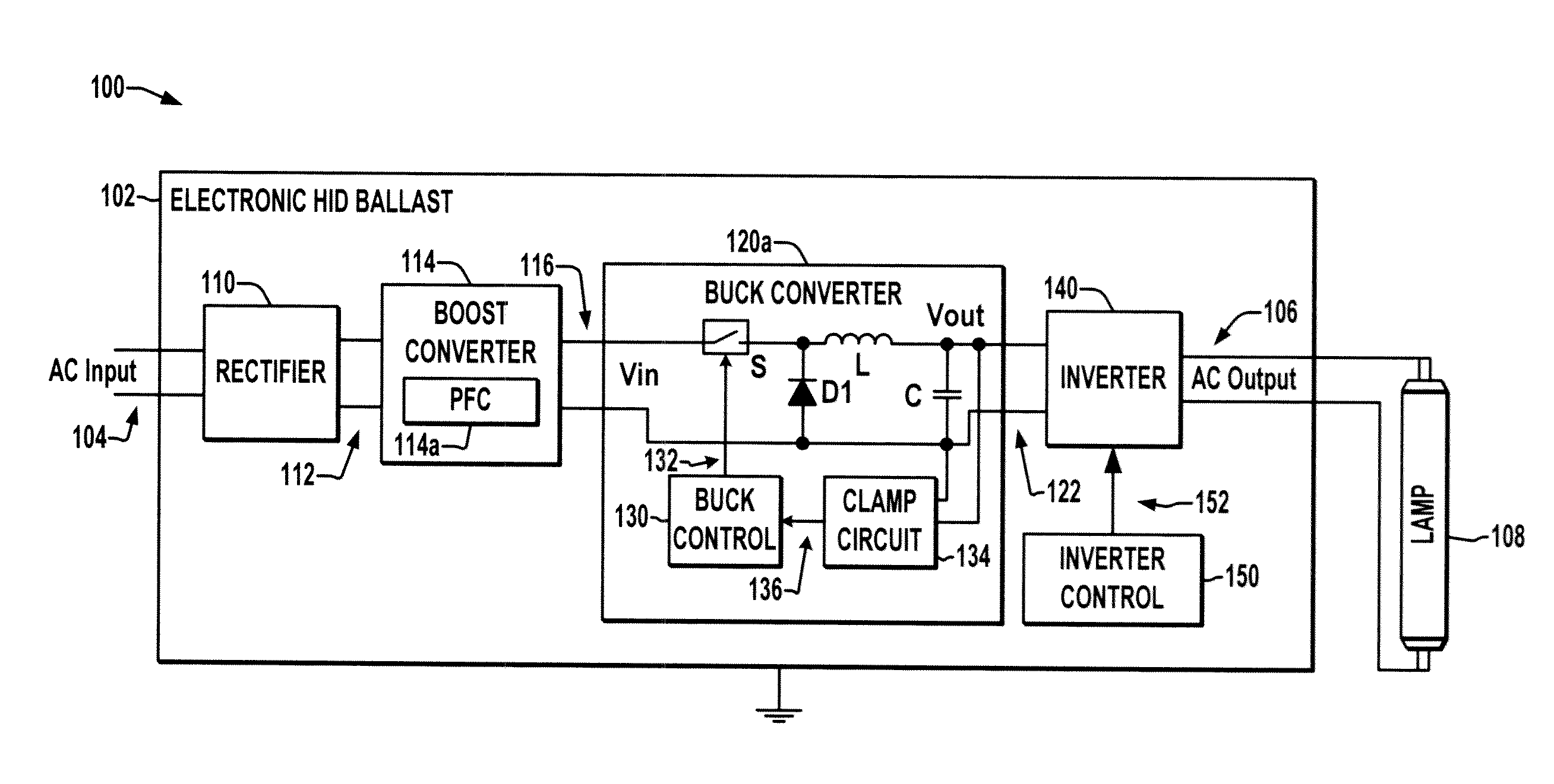
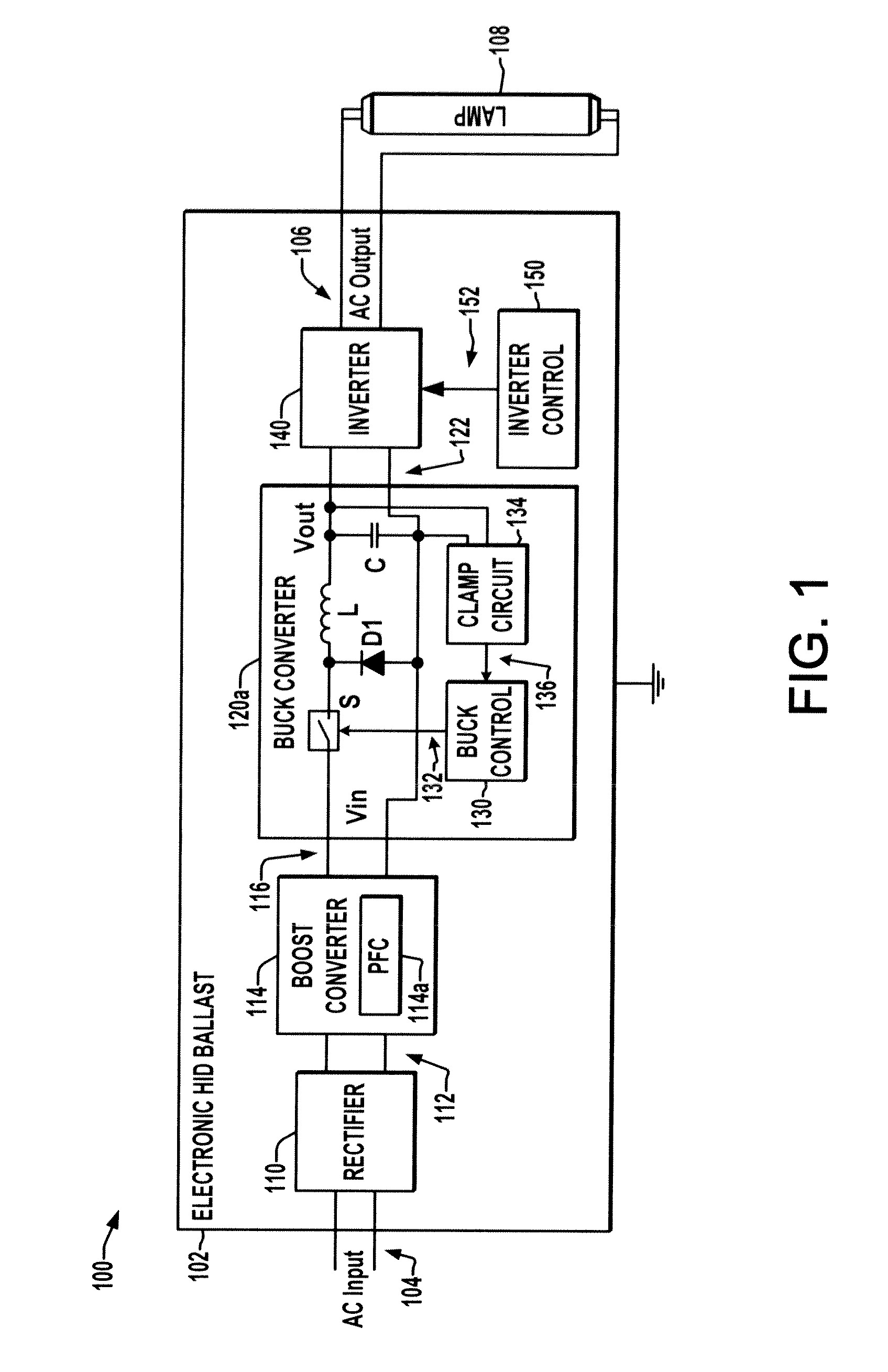
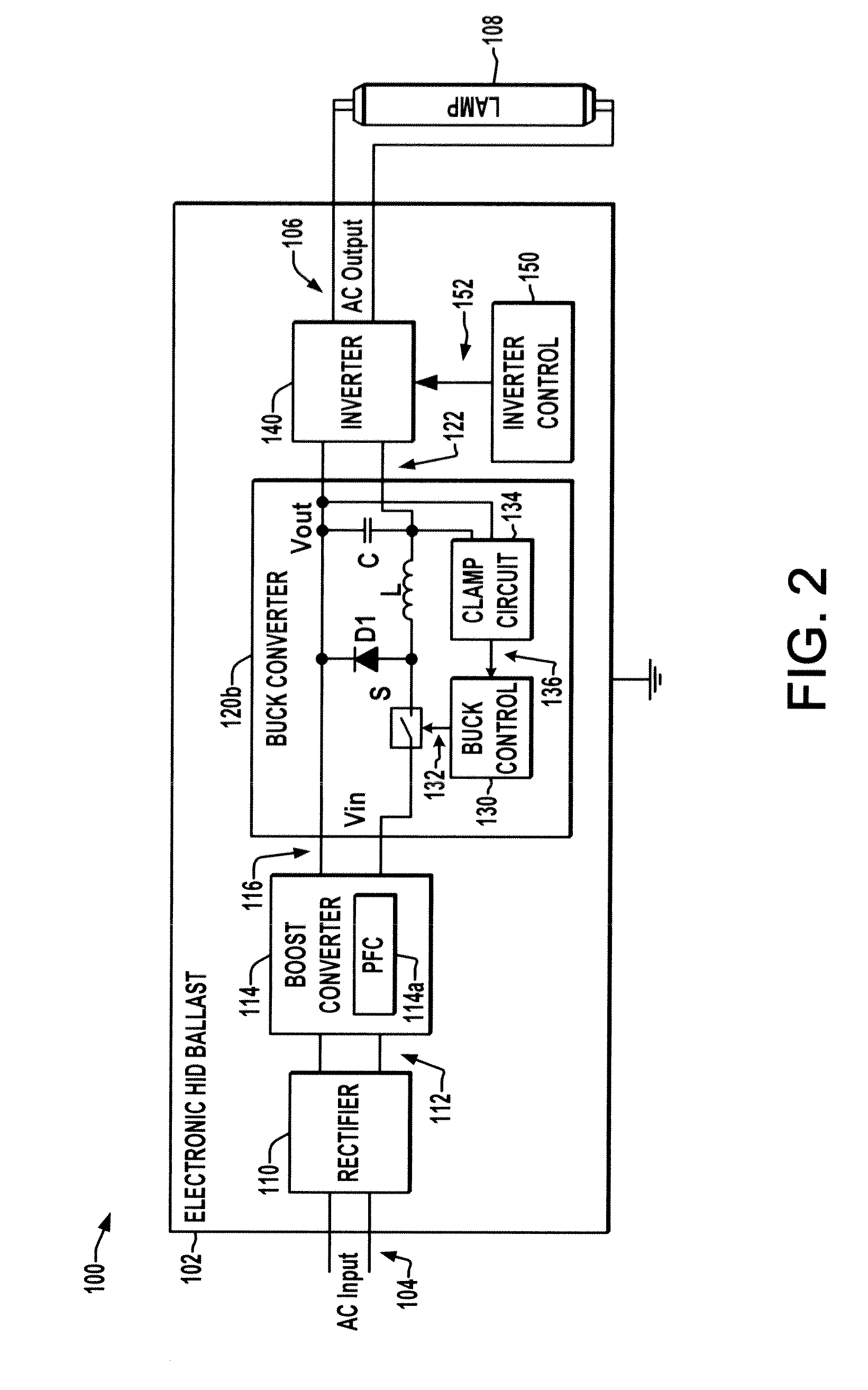
[0013]Referring now to the drawings, like reference numerals are used in the figures to refer to like elements throughout, and the various features are not necessarily drawn to scale. The present disclosure relates to HID ballasts and will be illustrated in connection with certain exemplary low frequency square wave electronic HID ballasts that can be operated by fixed or universal AC input voltages.
[0014]FIGS. 1 and 2 illustrate exemplary artificial lighting systems 100 in which an electronic HID ballast 102 receives power from an AC supply source 104 and provides an AC output 106 to drive a discharge lamp 108. The ballast 102 includes a rectifier 110 that receives and rectifies single or multi-phase AC power from a ballast input 104, where any form of active or passive, full or half-wave rectifier 110 may be employed, such as a full bridge rectifier having four diodes (not shown) in one embodiment. The rectifier 110 has an output 112 providing a rectified DC voltage to boost conve...
PUM
 Abstract
Description
Claims
Application Information