Touch panel

a technology of touch panel and touch pad, which is applied in the field of touch panel, can solve the problems of complex manufacturing process, difficulty in efficiently operating products using only the keyboard and mouse, and current input device technology exceeding the level of general functions, so as to prevent the resistance of the bridge and the connecting unit from abruptly increasing

Inactive Publication Date: 2011-12-15
SAMSUNG ELECTRO MECHANICS CO LTD
View PDF2 Cites 56 Cited by
  • Summary
  • Abstract
  • Description
  • Claims
  • Application Information

AI Technical Summary

Benefits of technology

[0015]The present invention has been made in an effort to provide a touch panel that forms two or more bridge patterns and connection patterns by dividing a bridge and a connecting unit to improve visibility of the touch panel and prevent terminal resistance of the bridge and the connecting unit from abruptly increasing.

Problems solved by technology

While the rapid advancement of the information-based society has been widening the use of computers more and more, there have been occurring the problems of it being difficult to efficiently operate products using only the keyboard and mouse as being currently responsible for the input device function.
Furthermore, current techniques for input devices exceed the level of fulfilling general functions and thus are progressing towards techniques related to high reliability, durability, innovation, designing and manufacturing.
Even though the self capacitive touch panel has a simple driving scheme, it has a complicated structure in that a plurality of electrode patterns should be separately formed and the electrode wirings should be connected to each of the electrode patterns, such that a manufacturing process thereof is complicated.
However, the bridge of the touch panel according to the prior art is formed to have a predetermined width or more so that it may be recognized by a user, thereby degrading visibility of the touch panel.
However, if the width of the bridge is narrowed, terminal resistance of the bridge abruptly increases to degrade the performance of the touch panel.
In addition, parasitic capacitance is generated between the bridge and electrode patterns under the bridge to operate as noise in recognizing the touch.

Method used


Image

  • Touch panel
  • Touch panel
  • Touch panel

Examples


Embodiment Construction

[0033]Various objects, advantages and features of the invention will become apparent from the following description of embodiments with reference to the accompanying drawings.

[0034]The terms and words used in the present specification and claims should not be interpreted as being limited to typical meanings or dictionary definitions, but should be interpreted as having meanings and concepts relevant to the technical scope of the present invention based on the rule according to which an inventor can appropriately define the concept of the term to describe most appropriately the best method he or she knows for carrying out the invention.

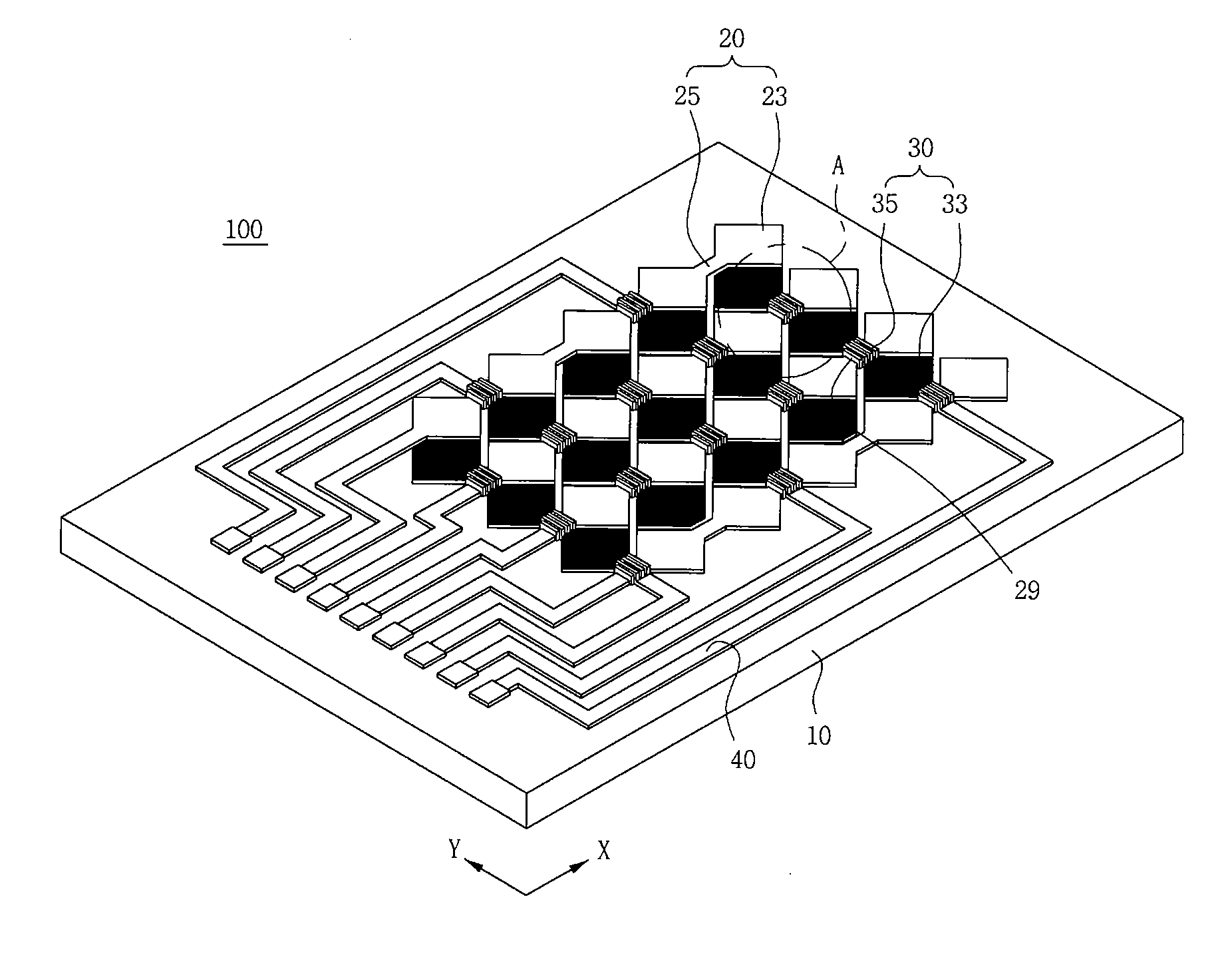
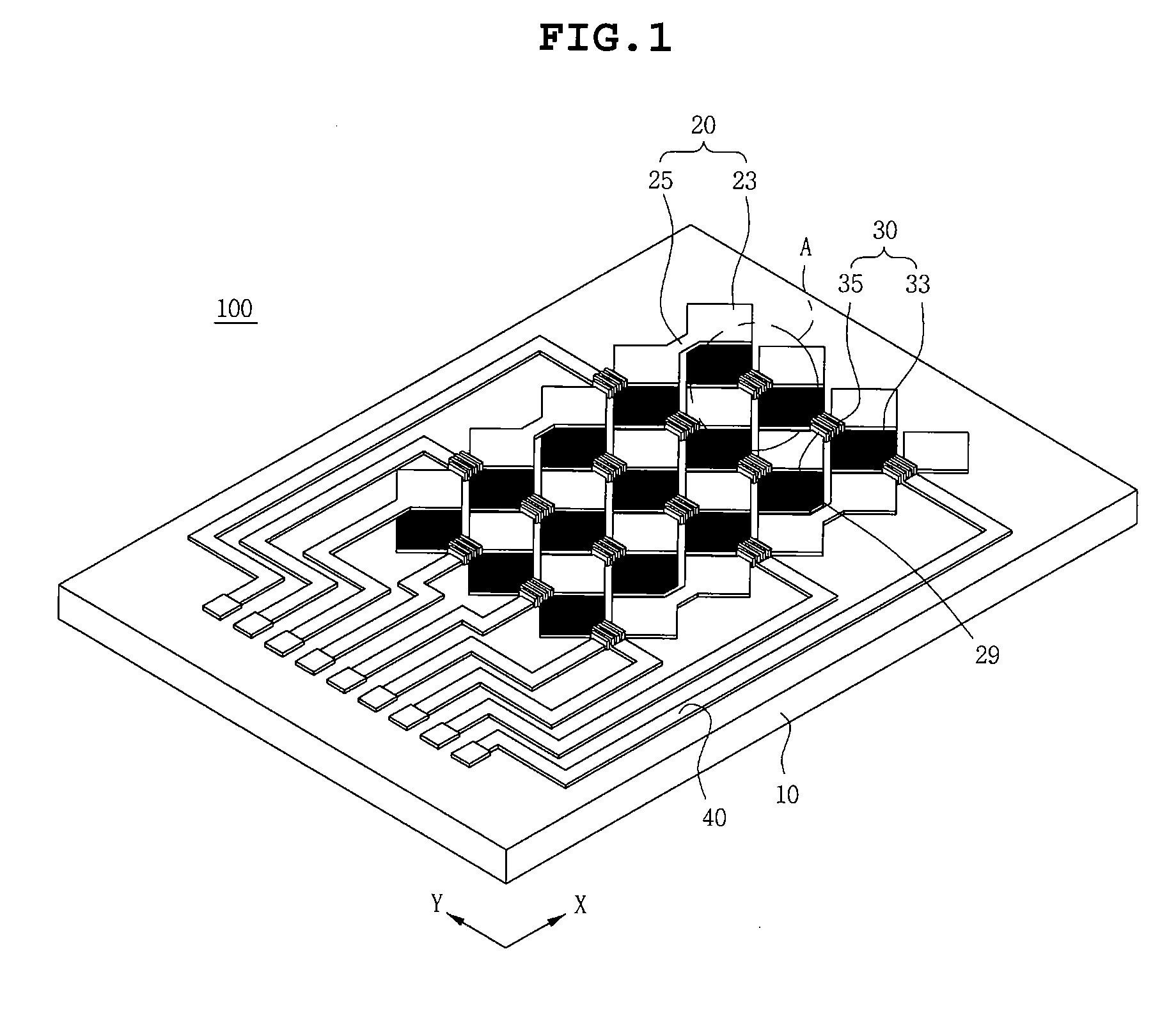
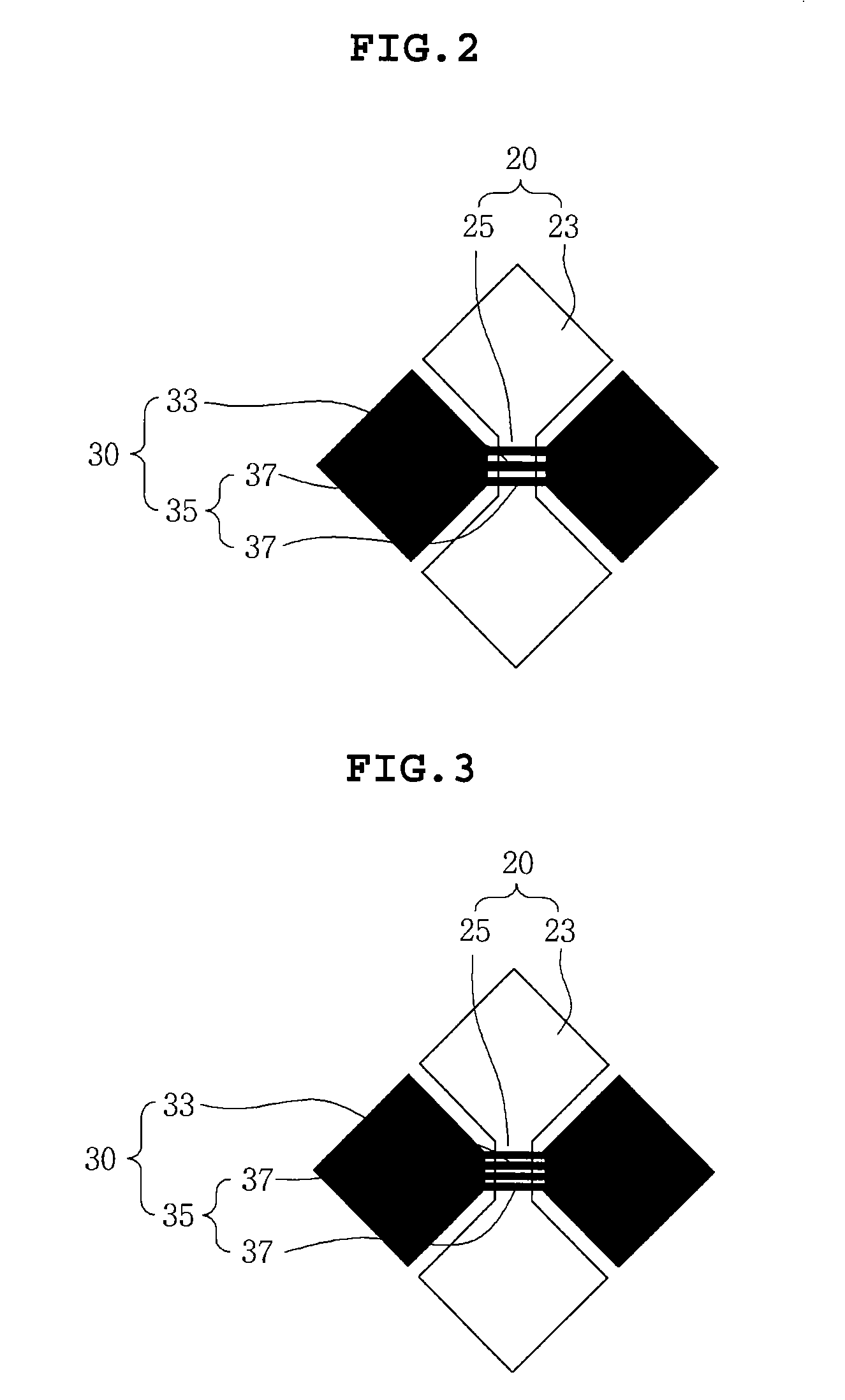
[0035]The above and other objects, features and advantages of the present invention will be more clearly understood from the following detailed description taken in conjunction with the accompanying drawings. In the specification, in adding reference numerals to components throughout the drawings, it is to be noted that like reference numerals designat...


PUM


Abstract

Disclosed herein is a touch panel 100 including: a transparent substrate 10, first electrode patterns 20 that are formed on one surface of the transparent substrate 10 and include a plurality of first sensing units 23 and connecting units 25 connecting adjacent first sensing units 23, and second electrode patterns 30 that are formed on one surface of the transparent substrate 10 vertically with the first electrode patterns 20 and include a plurality of second sensing units 33 and bridges 35 connecting the adjacent second sensing units 33 to be spaced apart from the connecting units 25, wherein the bridge 35 is divided to form two or more bridge patterns 37. The bridge is divided to form two or more bridge patterns so that a user cannot recognize the bridge, thereby making it possible to improve visibility of the touch panel.

Description

CROSS REFERENCE TO RELATED APPLICATION[0001]This application claims the benefit of Korean Patent Application No. 10-2010-0054403, filed on Jun. 9, 2010, entitled “Touch Panel”, which is hereby incorporated by reference in its entirety into this application.BACKGROUND OF THE INVENTION[0002]1. Technical Field[0003]The present invention relates to a touch panel.[0004]2. Description of the Related Art[0005]Alongside the growth of computers using digital technology, devices assisting the computers have also been developed, and personal computers, portable transmitters and other personal information processors execute processing of text and graphics using a variety of input devices such as a keyboard and a mouse.[0006]While the rapid advancement of the information-based society has been widening the use of computers more and more, there have been occurring the problems of it being difficult to efficiently operate products using only the keyboard and mouse as being currently responsible fo...

Claims


Application Information

Patent Timeline
Patent Type & Authority Applications(United States)
IPC IPC(8): G06F3/045
CPCG06F2203/04111G06F3/044G06F3/0446G06F3/0448G06F3/0445G06F2203/04103
Inventor KIM, HYUN JUNLEE, KYOUNG HOCHAE, KYOUNG SOOLEE, JONG YOUNG
Owner SAMSUNG ELECTRO MECHANICS CO LTD
Why Eureka
Try Eureka