
Autospectroscopic display device and method for operating an auto-stereoscopic display device

Inactive Publication Date: 2011-12-15
SONY ERICSSON MOBILE COMM AB
View PDF8 Cites 71 Cited by
  • Summary
  • Abstract
  • Description
  • Claims
  • Application Information

AI Technical Summary

Benefits of technology

[0010]Accordingly, even so the position of the viewer may change only by a small degree, e.g. from the normal (an axis perpendicular to the display section) to the display section, the scene is perceived by the viewer as if the viewer were looking at the scene in a second viewing direction under a second angle larger than the actual viewing angle between the viewer and the display section. Therefore, when the viewing angle is changed by a movement of the viewer, the images provided to the eyes may be images corresponding to an even larger viewing angle, i.e. a virtual viewing angle, than the actual viewing angle after movement so that the 3D effect can be exaggerated and the experienced visual comfort zone can be virtually extended. For example, a viewer looking perpendicularly on the display section receiving two images in a first pair of angular directions moves by 4° to the left and experiences a virtual viewing angle corresponding to a 6° movement. Here, the visual comfort zone can be defined as a zone in which the two images sent out in the first pair of angular directions can still be seen by the left and right eyes, respectively.
[0023]Another embodiment of the invention provides a method for operating an auto-stereoscopic display device for providing a three-dimensional image of a scene to a viewer, comprising the steps of sending out two images in at least a first pair of angular directions having a left angular direction and a right angular direction suitable for being looked at respectively by a left eye and a right eye of the viewer located at a particular position, the two images being sent out in the first pair of angular directions to confer a three-dimensional effect as if the viewer were looking at the scene in a first viewing direction under a first angle, and sending out two other images in a second pair of angular directions having a left angular direction and a right angular direction suitable for being looked at respectively by a left eye and a right eye of the viewer located at another particular position, the two other images being sent out in the second pair of angular directions to confer a three-dimensional effect as if the viewer were looking at the scene in a second viewing direction under a second angle, wherein the difference between the second angle and the first angle is larger than the difference between the angle of the right angular direction of the second pair and the angle of the right angular direction of the first pair and larger than the difference between the angle of the left angular direction of the second pair and the angle of the left angular direction of the first pair. Accordingly, the experienced visual comfort zone can be extended.

Problems solved by technology

The equipment for such 3D systems to perceive 3D images is complex and expensive and viewers are reluctant to wear bulky shutter glasses.
Although this technology allows in general to experience depth and to look “in between” different layers or depth by changing the viewing angle by tilting the display or moving the head to see things that were previously hidden, the visual zone is quite limited.
In detail, since the selection of different images for different eyes is based on a spatial separation of images by separate directions for different images, a large movement of the viewer leads to losing the image originally provided for the left eye and losing the image originally provided for the right eye so that no image is seen in the left eye and the image for the left eye is seen in the right eye, for example, if the viewer moved to the left.

Method used


Image

  • Autospectroscopic display device and method for operating an auto-stereoscopic display device
  • Autospectroscopic display device and method for operating an auto-stereoscopic display device
  • Autospectroscopic display device and method for operating an auto-stereoscopic display device

Examples


Embodiment Construction

[0033]Embodiments of the invention are described with reference to the figures and should serve to provide the skilled person with a better understanding of the invention. It is noted that the following description contains examples only and should not be construed as limiting the invention.

[0034]In the following, similar or same reference signs indicate similar or same elements.

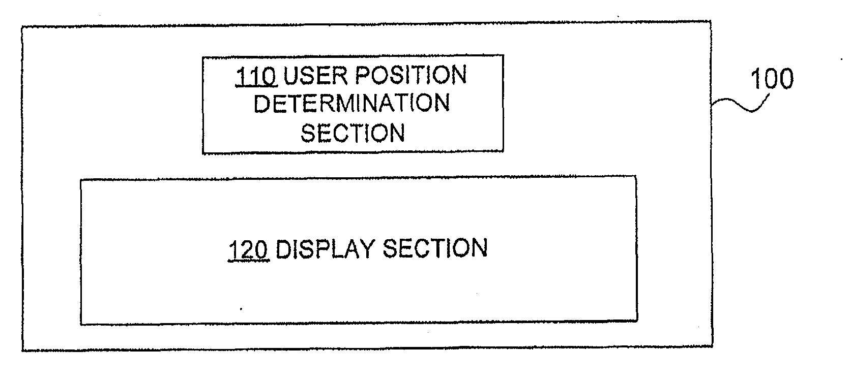
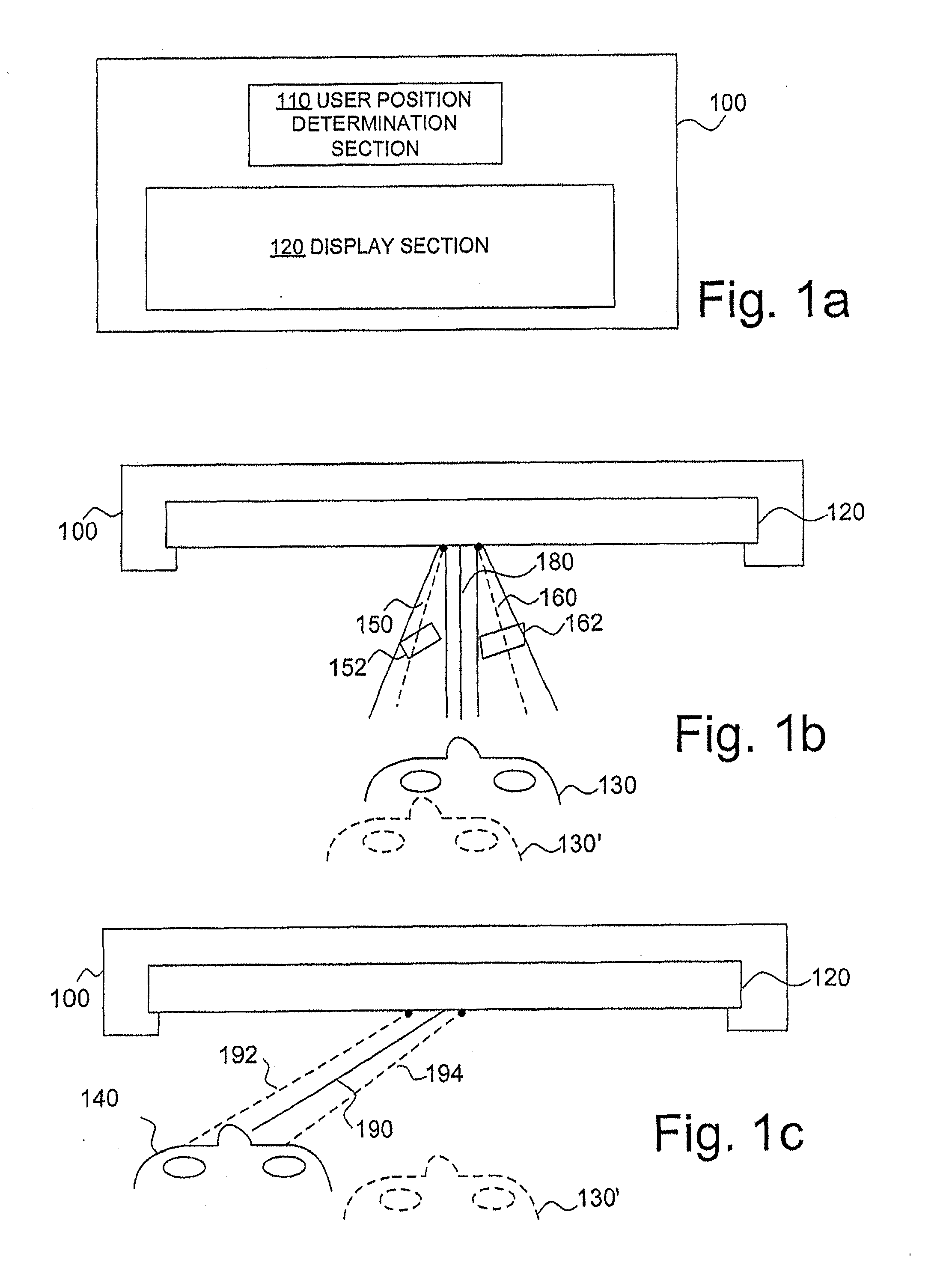
[0035]FIG. 1A illustrates elements of an auto-stereoscopic display device, which will be called in the following simply display device, according to an embodiment of the invention. FIG. 1A illustrates a display device 100 comprising a user position determination section 110 and a display section 120.

[0036]The user position determination section 110 is a determination section adapted to determine the position of a viewer with respect to the display device 100. In a common use case, the viewer is positioned in front of the display section 120 and watches images on the display section 120, such as a scene of a ...


PUM


Abstract

The present invention relates to an auto-stereoscopic display device and a method for operating an auto-stereoscopic display device for providing a three-dimensional image of a scene to a viewer so as to extend the experienced visual comfort zone of a viewer. A display device comprises a user position determination section operable to determine a position of the viewer with respect to said display device, and a display section operable to send out two images in at least a first pair of angular directions having a left angular direction and a right angular direction suitable for being looked at respectively by a left eye and a right eye of the viewer located at a particular position, wherein said display section is configured to send out the two images in said first pair of angular directions to confer a three-dimensional effect as if the viewer were looking at the scene in a first viewing direction under a first angle.

Description

FIELD OF THE INVENTION[0001]The present invention relates to an auto-stereoscopic display device and a method for operating an auto-stereoscopic display device for providing a three-dimensional image of a scene to a viewer, and in particular to an auto-stereoscopic display device having a user position determination section and to an auto-stereoscopic display device sending out images in at least two pairs of angular directions, so-called multi-view auto-stereoscopic display device.BACKGROUND[0002]In recent years, there has been rapid development in new display technologies, such as new displays for TV-sets and computer monitors replacing cathode ray tube (CRT) displays. Today, displays are mostly based on LCD or plasma technology. Screen sizes vary from a couple of centimeters to more than two meters with a large amount of pixels providing a much higher resolution than supported by common television signals.[0003]To further enhance the viewer's experience, flat screens with three-d...

Claims


Application Information

Patent Timeline
IPC IPC(8): G06T15/00
CPCH04N13/0402H04N13/0477H04N13/045H04N13/0404H04N13/302H04N13/305H04N13/376H04N13/354
Inventor THORESSON, JOHAN
Owner SONY ERICSSON MOBILE COMM AB
Features
  • Generate Ideas
  • Intellectual Property
  • Life Sciences
  • Materials
  • Tech Scout
  • Unparalleled Data Quality
  • Higher Quality Content
  • 60% Fewer Hallucinations
Learn More