Pole with solar modules

Inactive Publication Date: 2011-12-15
ABL IP HLDG
View PDF10 Cites 19 Cited by
  • Summary
  • Abstract
  • Description
  • Claims
  • Application Information

AI Technical Summary

Benefits of technology

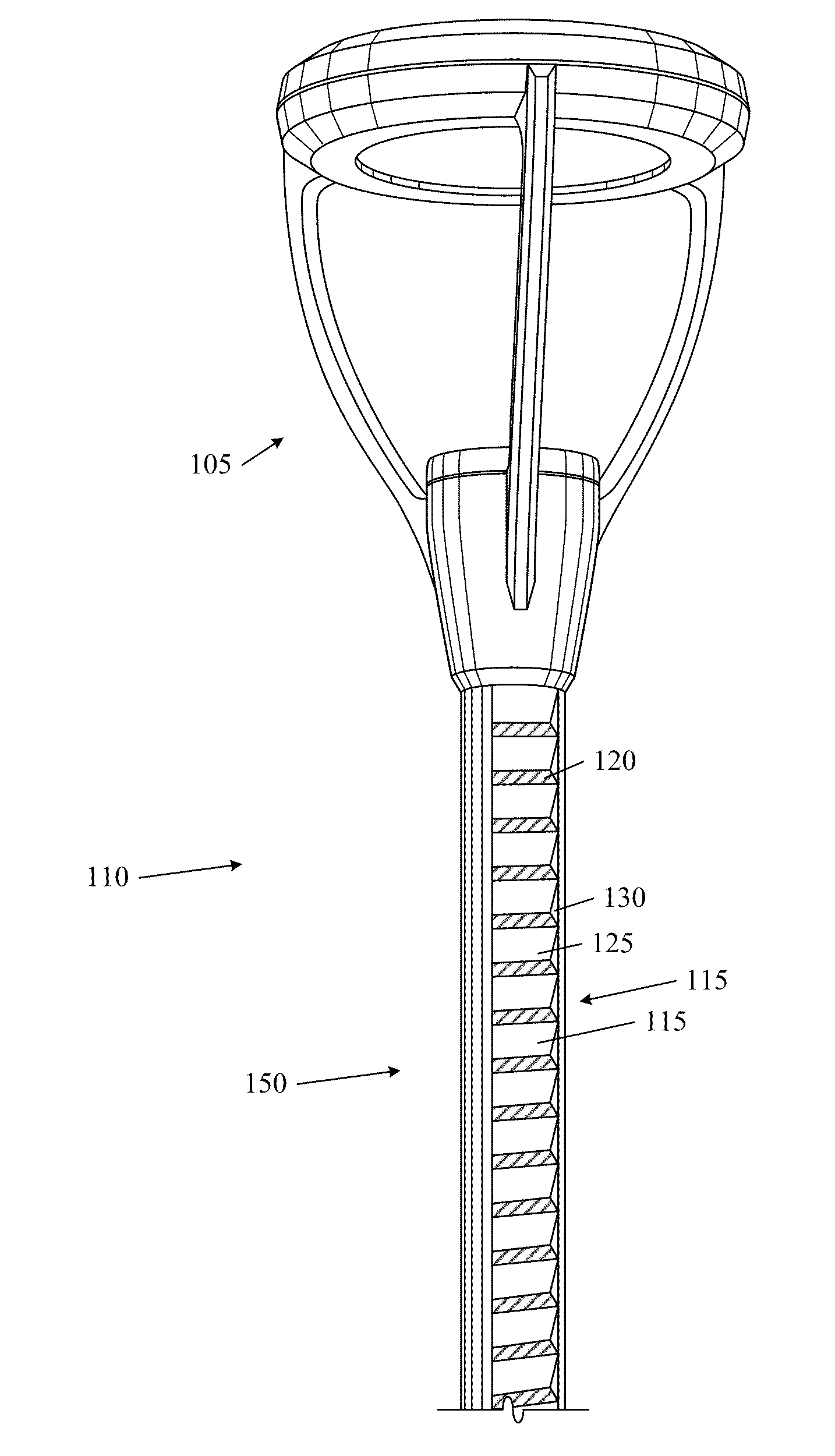
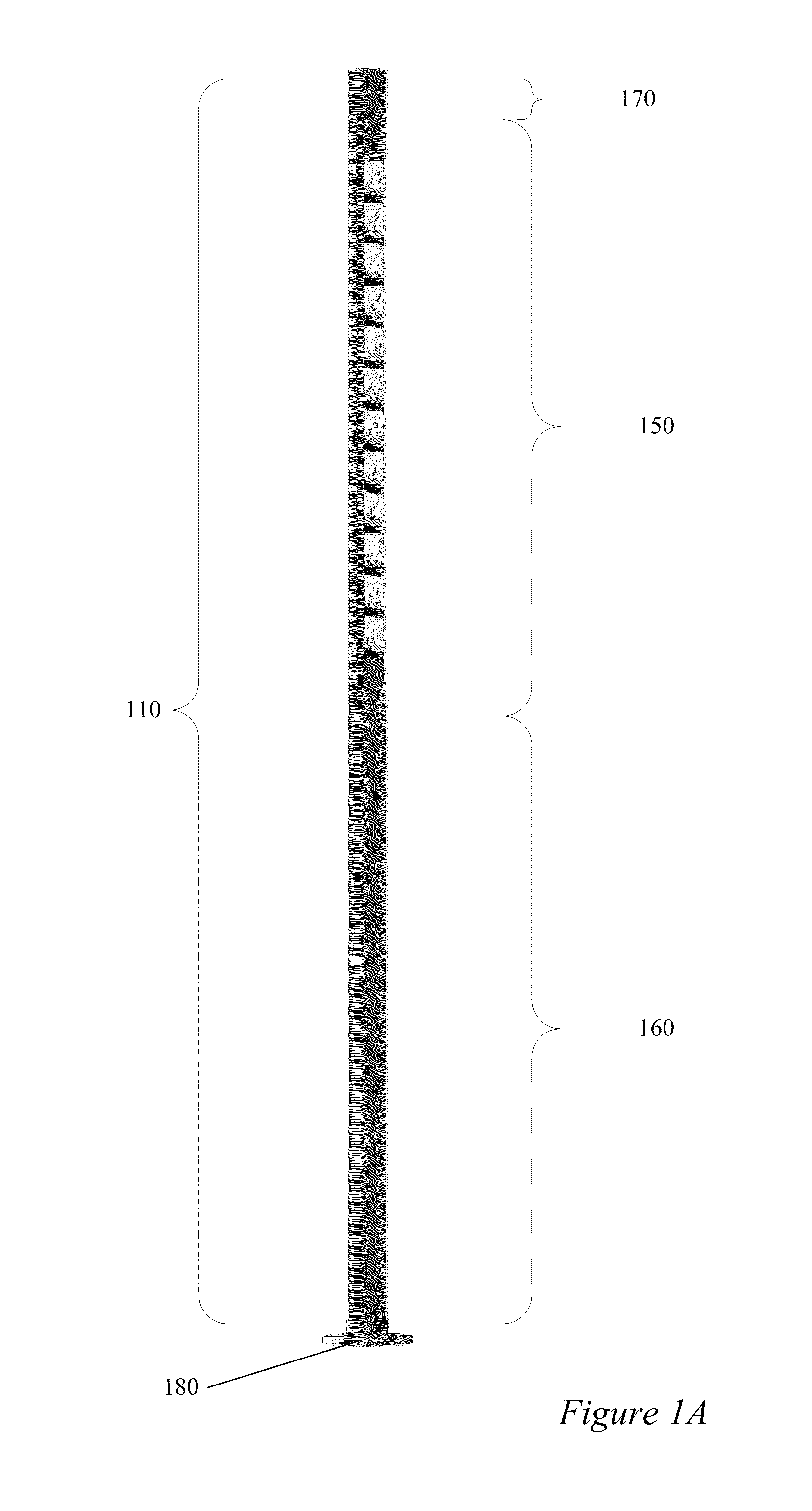
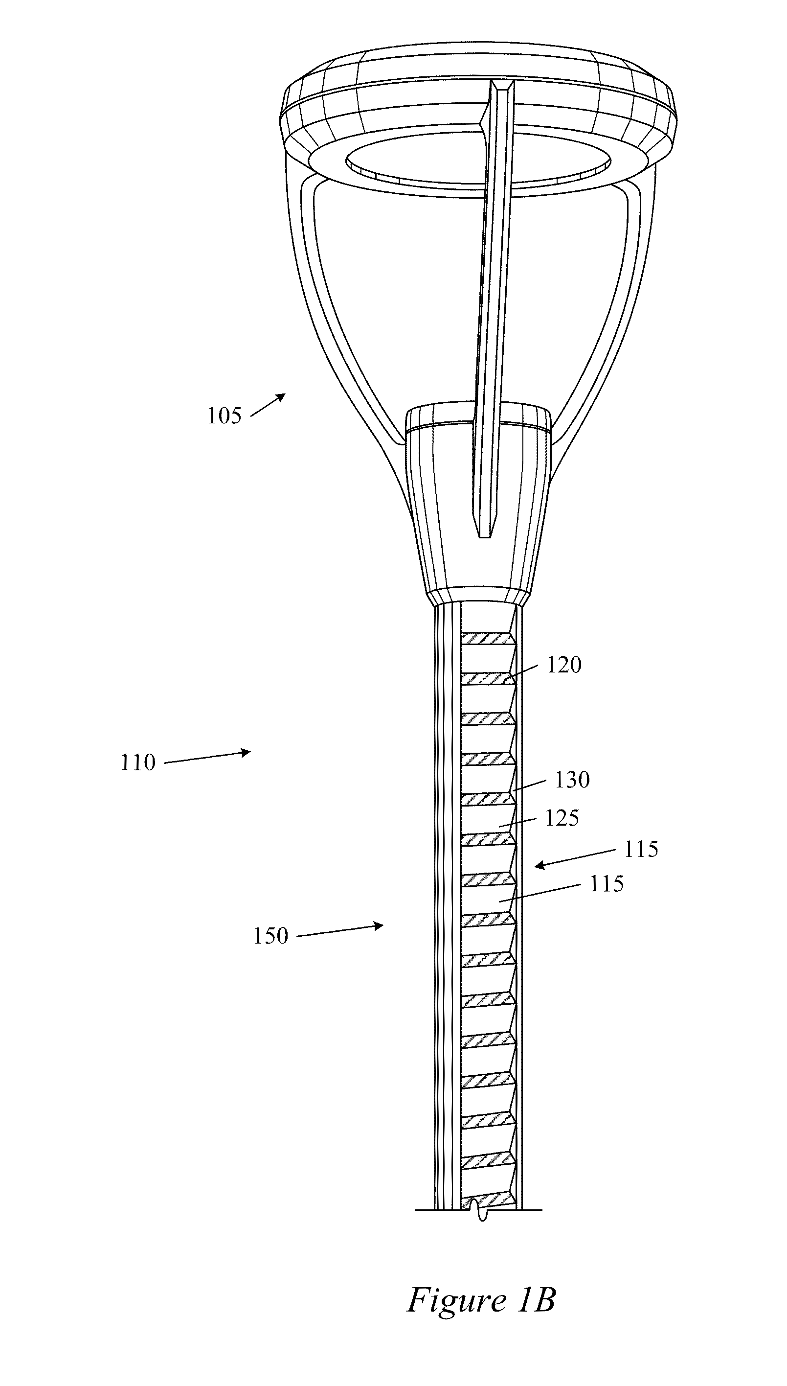
[0004]Embodiments of the present invention relate to poles having solar power capabilities and, more specifically, poles that include solar modules (hereinafter “solar poles”). In some embodiments, the solar modules are positioned within a solar pole. A solar module can include, for example, a solar cell and at least one reflective surface situated near the solar cell. The reflective surface reflects and focuses light onto the solar cell, thereby increasing the amount of light and energy collected by individual solar cells.

Problems solved by technology

However, few existing autonomous systems are capable of providing light levels equal to that of conventional electric lighting systems at conventional pole spacing and extended periods of uncooperative weather are problematic.
In addition, autonomous systems are relatively expensive and require periodic maintenance.
Pole and installation costs are higher as well due to the presence of additional system components and their impact on wind loading.
Both wind turbines and solar panels create wind resistance, which translates to an increased overturning moment, especially when the turbines or panels are located near the top of the pole, as is typical.
The pole and its concrete base must also both be sized to resist this overturning moment, significantly increasing installation costs.
Another drawback of conventional autonomous systems has to do with aesthetics.
Many people consider large solar panels and wind turbines unsightly.

Method used


Image

  • Pole with solar modules
  • Pole with solar modules
  • Pole with solar modules

Examples


Embodiment Construction

[0020]The subject matter of embodiments of the present invention is described here with specificity to meet statutory requirements, but this description is not necessarily intended to limit the scope of the claims. The claimed subject matter may be embodied in other ways, may include different elements or steps, and may be used in conjunction with other existing or future technologies. This description should not be interpreted as implying any particular order or arrangement among or between various steps or elements except when the order of individual steps or arrangement of elements is explicitly described.

[0021]Embodiments of the present invention are directed toward poles with solar power generation capabilities. In some embodiments, a solar pole can include solar cells that are positioned within a pole. Reflective and / or refractive optics can be used to focus solar light onto the various solar cells. A solar pole may be coupled with an electrical grid and can provide power to t...


PUM


Abstract

Poles having solar power capabilities and, more specifically, poles that include solar modules (hereinafter “solar poles”) are disclosed. In some embodiments, the solar modules are positioned within a solar pole. A solar module can include, for example, a solar cell and at least one planar reflective surface situated near the solar cell. The reflective surfaces reflect and focus light onto the solar cells, thereby increasing the amount of light and energy collected by individual solar cells.

Description

CROSS-REFERENCES TO RELATED APPLICATIONS[0001]This is a non-provisional application that claims the benefit of commonly assigned U.S. Provisional Application No. 61 / 352,938, filed Jun. 9, 2010, entitled “Pole With Solar Modules,” the entirety of which is herein incorporated by reference for all purposes.BACKGROUND OF THE INVENTION[0002]Most lighting fixtures are powered directly by the national power grid. Given the prevailing emphasis on energy conservation and green energy sources, outdoor lighting systems are a compelling platform for the application of renewable energy technologies, such as wind and solar power generation. Some outdoor lighting systems include structural frameworks that can be used for more than one purpose. For example, a structure can include signage, lighting, roadway marking, etc. And outdoor lighting systems can incorporate renewable energy technologies with little negative impact on land use and planning. Moreover, outdoor lighting equipment provides a hig...

Claims


Application Information

Patent Timeline
IPC IPC(8): F21L4/08H01M10/46H02J4/00H01L31/052
CPCF21S9/035H01M10/465Y02E10/52H01L31/0547F24J2/523H02S40/38H02S20/10Y02E10/47F24S25/10Y02E60/10Y02E70/30
Inventor LEADFORD, KEVIN FRANKLINNELSON, PETER K.
Owner ABL IP HLDG
Why Eureka
Try Eureka