Water heating system and a method of operating same

a water heating system and water heating technology, applied in the field of water heating systems and a method of operating same, can solve the problems of water wastage, type of gas wastage, heater takes some time to come up to temperature,

Inactive Publication Date: 2011-12-15
DUX MFG
View PDF0 Cites 38 Cited by
  • Summary
  • Abstract
  • Description
  • Claims
  • Application Information

AI Technical Summary

Benefits of technology

[0069]The method preferably also comprises varying the speed of the pump, so as to vary the dwell time of the water passing through the heater and thus the temperature of the heated water at the outlet of the heater.

Problems solved by technology

The first disadvantage relates to water wastage.
The second disadvantage relates to two types of gas wastage.
In the case of a shower, the heater takes some time to come up to temperature and the cool-to-warm water delivered in the intervening heating period is often dumped to waste by the householder.
In that situation, gas is used to solely go through a start up phase and heated water is left in the pipes, which then cools and is thus wasted.

Method used


Image

  • Water heating system and a method of operating same
  • Water heating system and a method of operating same
  • Water heating system and a method of operating same

Examples


first embodiment

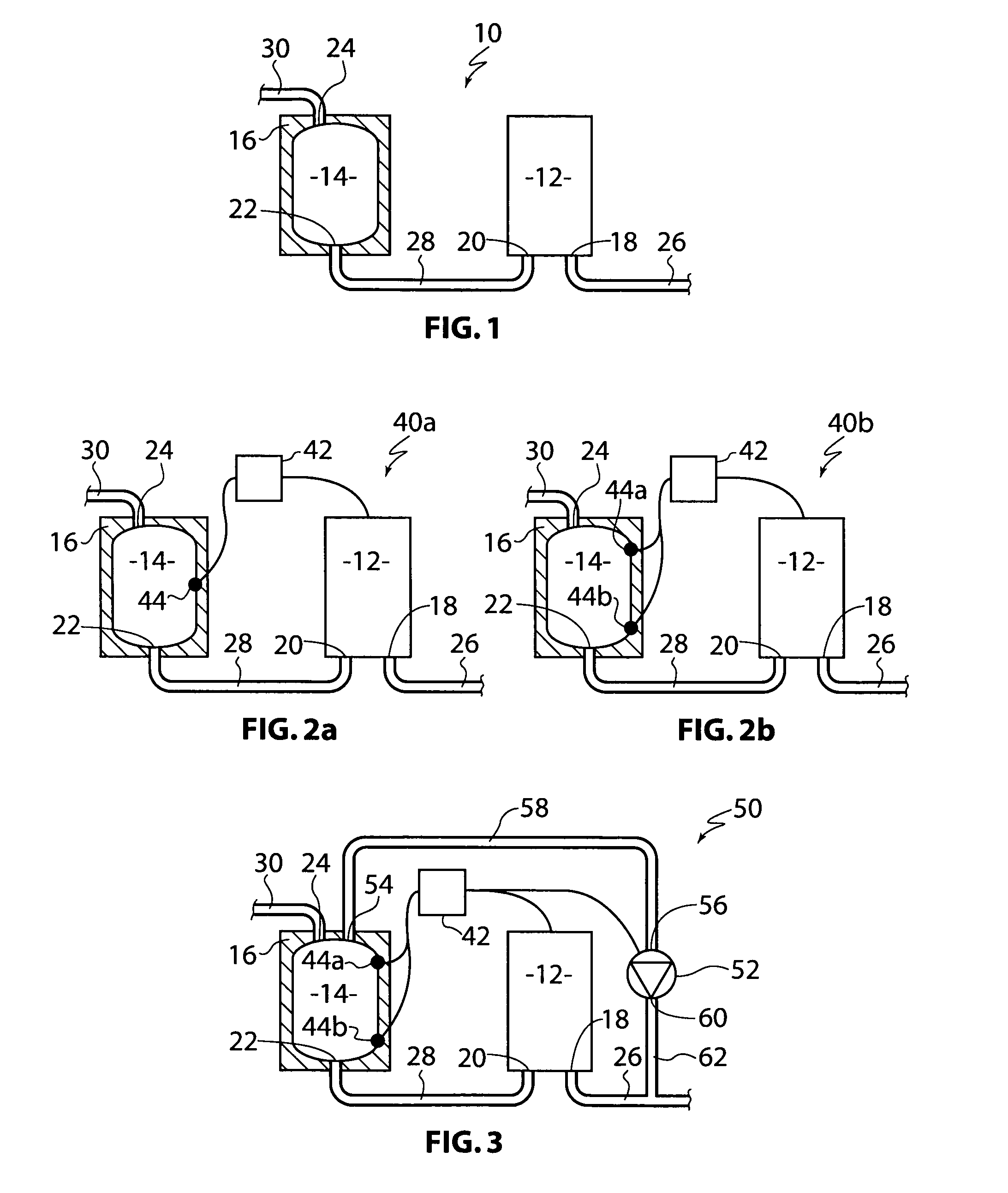
[0116]FIG. 1 shows a water heating system 10 comprising a gas instantaneous-type water heater 12, preferably of 4, 5 or 6-Star rating. The burners in the heater 12 are automatically energised upon sensing flow of water through the heater 12. The system 10 also includes a (buffer) water storage tank 14, preferably 4-50 litres in volume. The tank 14 is encased in insulation 16. The heater 12 has an inlet 18 and an outlet 20. The tank 14 has an inlet 22 and an outlet 24. The inlet 18 of the heater 12 is connected to a mains water supply pipe 26. The outlet of the heater 12 is connected to the inlet 22 of the tank 14 by a pipe 28. The outlet 24 of the tank 14 is connected to a user-controlled outlet device, such as a hot tap (not shown), by a pipe 30.

[0117]When the tap is initially actuated by a user, water flows from the mains supply pipe 26 into the heater 12 and is heated by the gas burners therein. The heated water then flows through pipe 28 into the tank 14 and, after the tank 14 i...

second embodiment

[0118]A first version 40a of water heating system is shown in FIG. 2a. The water heating system 40a is similar to the water heating system 10 shown in FIG. 1 and like features have been indicated with like reference numerals. However, the water heating system 40a also includes a controller 42. The controller 42 receives signals indicative of water temperature in the (4-50 litre) tank 14 from a sensor 44 which is positioned near the middle of the tank 14. The controller 42 is also connected to the heater 12 and is able to control whether or not the heater 12 is energised in response to water flow. As the heater 12 does not energise automatically in response to water flow, it can be simplified and is thus less expensive.

[0119]If the sensor 44 indicates to the controller 42 a water temperature of about 55 Degrees C. or less, then the controller 42 will energise the heater 12. If the sensor 44 indicates to the controller 42 a water temperature between about 55 Degrees C. and about 75 De...

third embodiment

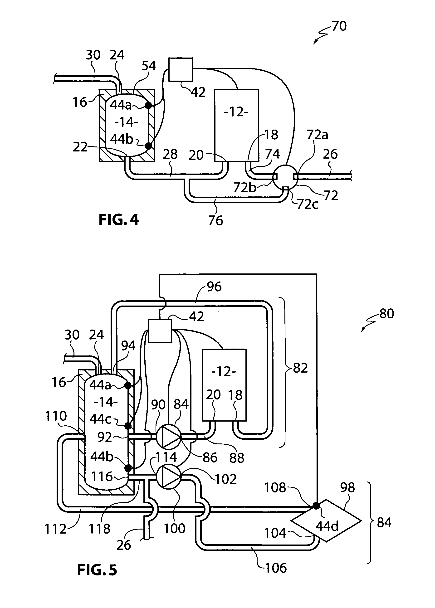
[0123]FIG. 3 shows a water heating system 50. The water heating system 50 is similar to the water heating systems 40a and 40b shown in FIG. 2a and FIG. 2b and like features have been indicated with like reference numerals. However, in the water heating system 50, the controller 42 is also connected to a pump 52. The tank 14 also includes an additional outlet 54 which is connected to an inlet 56 of the pump 52 by a pipe 58. An outlet 60 of the pump 52 is connected to the mains water supply pipe 26 by a pipe 62.

[0124]If the second / bottom sensor 44b indicates to the controller 42 a water temperature of about 55 Degrees C. or less, then the controller 42 will energise the heater 12. If the first / top sensor 44a indicates to the controller 42 a water temperature of about 75 Degrees C. or more, then the controller 42 will not energise the heater 12 or, if operating, de-energise the heater 12. If the second / bottom sensor 44b indicates to the controller 42 a water temperature of about 55 Deg...


PUM


Abstract

A hot water system (10) comprising a water storage tank (14) and an instantaneous-type water heater (12). The water storage tank (14) has an inlet (22) and outlet (24). The instantaneous-type water heater (12) has an inlet (18), in fluid communication with a mains water supply (26), and an outlet (20), in fluid communication with the inlet (22) of the tank (14). The water heater (12) energises in response to a flow of water through the water heater (12).

Description

FIELD OF THE INVENTION[0001]The present invention relates to a water heating system and a method of operating same.[0002]The present invention has been primarily developed for use with gas instantaneous type water heaters and will be described hereinafter with reference to that application. However, the invention is not limited in this particular field of use and can also be used with electrical instantaneous-type heaters. In the United States of America, instantaneous-type water heaters are known as tank-less heaters.BACKGROUND OF THE INVENTION[0003]Known instantaneous type heaters have an inlet, connected to a mains water supply, and an outlet connected to, for example, a tap. The flow of water through the heater automatically energises the gas burners or electrical elements therein. This known arrangement has two disadvantages.[0004]The first disadvantage relates to water wastage. When a user activates a hot water tap, the user must wait for the mains supplied water to be heated,...

Claims


Application Information

Patent Timeline
Patent Type & Authority Applications(United States)
IPC IPC(8): F24H1/10
CPCF24D17/0031F24D19/1051F24H1/122F24D2240/26F24H9/2028F24D2220/042F24H9/2021F24H15/225F24H15/281F24H15/34F24H15/128F24H15/36F24H15/174F24H15/32
Inventor PUSSELL, PATRICK
Owner DUX MFG
Why Eureka
Try Eureka