[0007]It is an object of the present invention to provide an EGR control apparatus for an internal
combustion engine, which is capable of properly controlling an
inert gas amount of two types of EGR gas supplied to cylinders of the engine via two paths different from each other, thereby making it possible to ensure a stable combustion state and reduced exhaust emissions, and improve
operability.
[0010]In contrast, according to this EGR control apparatus, the first EGR gas amount and the second EGR gas amount are controlled such that when the combination of the load represented by the load parameter and the engine speed is in the predetermined region, the first
inert gas amount which is the amount of inert gas in the first EGR gas supplied to the cylinders exceeds the second inert gas amount which is the amount of inert gas in the second EGR gas supplied to the cylinders. Therefore, if the predetermined region is set to such a region that a large amount of low-temperature inert gas is required so as to lower the in-cylinder gas temperature or the compression end temperature, e.g. a region of high engine speed and
high load, it is possible to supply, in such a region, a large amount of a lower-temperature one of the first inert gas and the second inert gas to the cylinders, whereby it is possible to lower the in-cylinder gas temperature and the compression end temperature.
[0011]In addition, the first EGR gas amount and the second EGR gas amount are controlled such that as the engine speed is higher or the load represented by the load parameter is larger, the first inert gas amount more exceeds the second inert gas amount. Therefore, as the degree of demand of lower-temperature inert gas is higher because of the engine speed being higher or the load being larger, it is possible to appropriately supply a larger amount of low-temperature inert gas to the cylinders in accordance therewith. Further, under a high-engine speed condition or a high-load condition, the amount of intake air to the cylinders increases and time taken for gases in the intake passage to be conveyed to the cylinders is reduced, and hence it is possible to speedily supply the first inert gas and the second inert gas to the cylinders. With the above configuration, it is possible to appropriately control the amount of inert gas in the EGR gas supplied to the cylinders according to the degree of demand of low-temperature inert gas. This makes it possible to secure a stable combustion state, reduce exhaust emissions, and improve
operability (throughout the specification, “detection” as in “detection of the engine speed” and “detection of the load parameter” is by no means limited to direct detection of these parameters, but includes calculation of values thereof, and “supply of part of burned gases to the cylinders via a short path” includes causing part of burned gases to remain in combustion chambers of the cylinders without discharging the part out of the combustion chambers, and “inert gas amount” and “EGR amount” includes a flow rate of inert gas and a flow rate of EGR gas, respectively.)
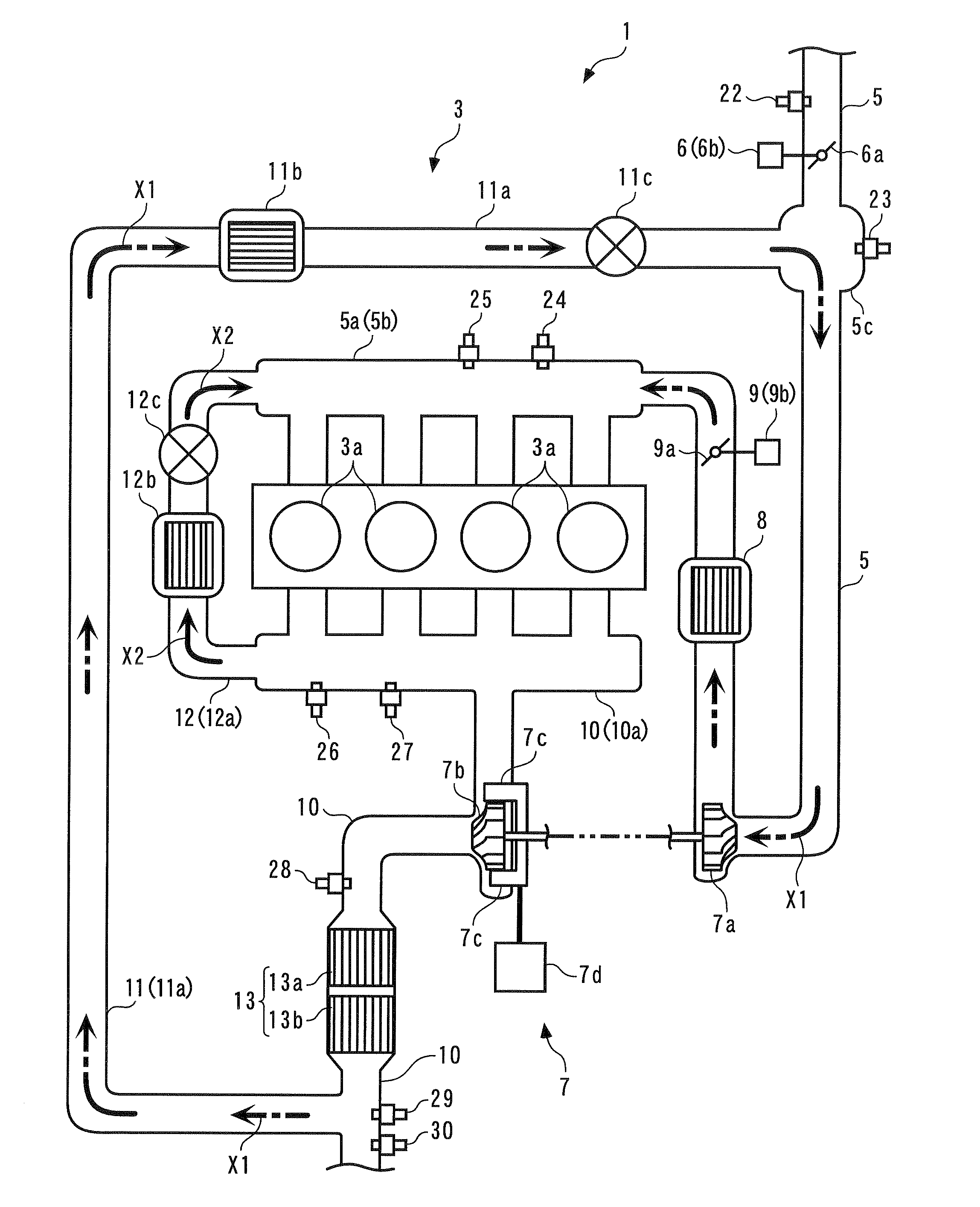
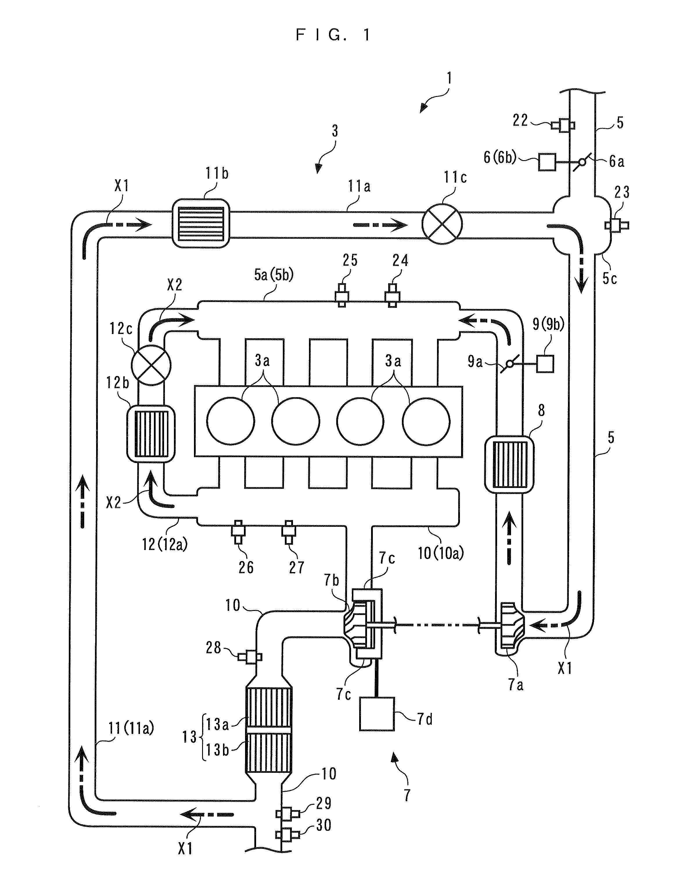
[0014]The second EGR device supplies the second EGR gas to the cylinders via a shorter path than the first EGR device supplies the first EGR gas to the cylinders, and has characteristics of shorter
dead time and higher responsiveness than the first EGR device. Therefore, even when the
rate of convergence of the second difference to 0 is set to be higher than the
rate of convergence of the first difference to 0, the first EGR device and the second EGR device can positively realize such convergence rates because of the difference in responsiveness therebetween, whereby it is possible to prevent the control of the first EGR device by the first EGR control means and the control of the second EGR device by the second EGR control means from interfering with each other. In addition to this, it is possible for the second EGR device, which is high in responsiveness, to accurately supply an amount of inert gas which cannot be secured by the first EGR device alone, which is low in responsiveness. For the reasons described above, it is possible to secure a stable combustion state and reduced
exhaust emission, and improve operability.
[0016]With the configuration of the preferred embodiment, using the predetermined response-designating control algorithms, the first EGR control input and the second EGR control input are calculated, respectively, such that the first difference and the second difference converge to 0. Therefore, it is possible to cause the first difference and the second difference to converge to 0 by exponential behaviors. This makes it possible to further improve the stability of the combustion state, further reduce exhaust emissions, and further improve operability.

