Methods and systems for boost control

a boost control and boost technology, applied in the direction of electric control, machines/engines, mechanical equipment, etc., can solve the problems of increasing the risk of condensation at both the compressor inlet and the charge air cooler outlet, damage to the blades, and introduction of water into the engine, so as to improve the peak power output, reduce the effect of exhaust emissions, and increase the dilution of the engin

Active Publication Date: 2016-02-16
FORD GLOBAL TECH LLC
View PDF37 Cites 33 Cited by
  • Summary
  • Abstract
  • Description
  • Claims
  • Application Information

AI Technical Summary

Benefits of technology

[0002]Engine systems may be configured with a boosting device, such as a turbocharger, for providing a boosted aircharge and improving peak power outputs. Therein a turbine is rotated using energy from an exhaust flow, the turbine then driving a compressor which delivers a boosted aircharge to the engine intake. In an effort to meet stringent federal government fuel economy standards, engine systems may also be configured with exhaust gas recirculation (EGR) systems wherein at least a portion of the exhaust gas is recirculated to the engine intake. For example, the EGR system may be a low-pressure EGR system (LP-EGR) that recirculates exhaust gas from downstream of an exhaust turbine to upstream of an exhaust compressor. EGR benefits include an increase in engine dilution, decrease in exhaust emissions, and improvements in fuel economy.
[0003]The compressor and other intake system components have temperature limitations, to avoid coking and / or thermal stress or damage. Therefore, the EGR is cooled substantially before introduction into the air induction system by a costly EGR cooler (different from the charge air cooler located downstream of the compressor). However, since EGR has relatively large water content (e.g., 8% water by mass for gasoline), the addition of LP-EGR at this substantially lower temperature to the intake at a pre-compressor location increases the risk of condensation at both a compressor inlet as well as a charge air cooler outlet. Specifically, under cold ambient conditions, when the humid EGR is mixed with cold ambient air, water droplets can form. Water droplets impacting the compressor blades which are rotating at high speeds (e.g., 200,000 rpm or above) can cause damage to the blades. In addition, since the ingested water slows the rate of combustion, the introduction of water into the engine can increase the likelihood of misfire events.
[0004]To address these issues, engine control systems may employ various approaches to limit the condensation. One example approach is shown by Rimnac et al. in U.S. Pat. No. 6,681,171. Therein, if conditions favoring EGR condensation are determined, intake manifold temperatures are increased by redirecting some or all of the EGR flow to avoid the EGR cooler. Additionally, some or all of the charge air is redirected from an outlet of the compressor to the engine intake, while bypassing the charge air cooler. As a result, a higher effective intake air temperature is provided which reduces the likelihood of condensation.
[0006]In one example, some of the above issues may be addressed by a method for an engine comprising: mixing compressor recirculation flow from downstream of a charge air cooler with exhaust gas, and delivering the mixture to a compressor inlet. In this way, hot EGR that has not been cooled by an EGR cooler can be mixed with cooled compressor recirculation flow to improve temperature and relative humidity management of the compressor inlet air.
[0008]In this way, compressor temperature management is improved. By not requiring cooled EGR, the need for a dedicated EGR cooler is reduced. For example, the cooler may be dramatically downsized or removed from the design, providing component reduction benefits. By using cooled compressor recirculation flow to cool the EGR, a relative humidity and temperature at the compressor inlet, as well at a compressor outlet, can be tuned more precisely. In particular, the compressor inlet and outlet temperatures can be maintained within a range that improves turbocharger performance. By reducing the formation of condensation at the compressor inlet, issues related to the ingestion of condensate (such as misfire, degradation of compressor blades, and engine stall) can be better addressed. Further, use of cooled compressor recirculation flow can concurrently improve the compressor's margin to surge, while also reducing thermal amplification effects that can occur with the use of warm compressor recirculation flow. Overall, boosted engine performance is improved.

Problems solved by technology

However, since EGR has relatively large water content (e.g., 8% water by mass for gasoline), the addition of LP-EGR at this substantially lower temperature to the intake at a pre-compressor location increases the risk of condensation at both a compressor inlet as well as a charge air cooler outlet.
Water droplets impacting the compressor blades which are rotating at high speeds (e.g., 200,000 rpm or above) can cause damage to the blades.
In addition, since the ingested water slows the rate of combustion, the introduction of water into the engine can increase the likelihood of misfire events.
However, the inventors herein have identified potential issues with such an approach.
It also does not address the compressor temperature limitations.

Method used


Image

  • Methods and systems for boost control
  • Methods and systems for boost control
  • Methods and systems for boost control

Examples


Embodiment Construction

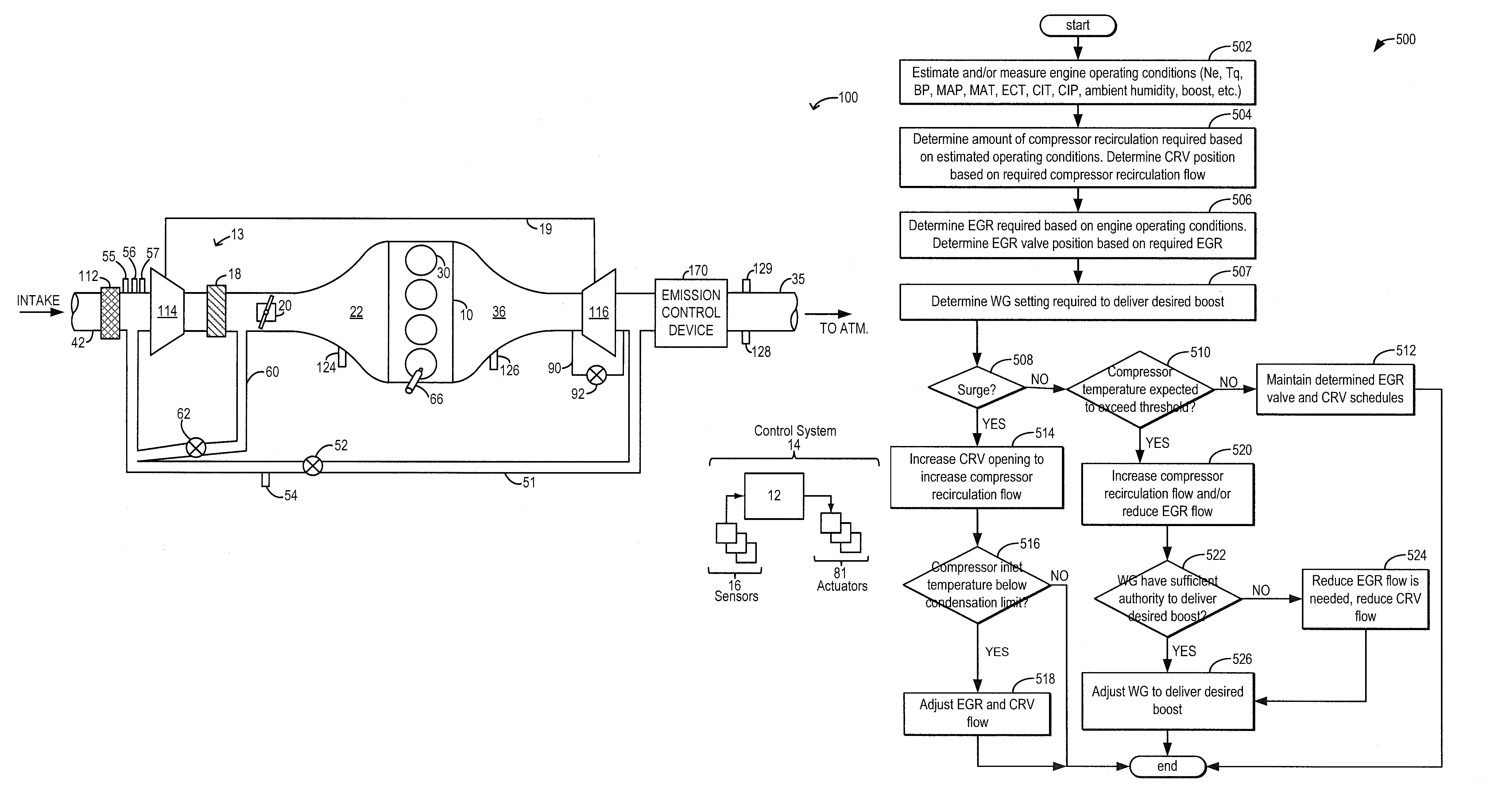
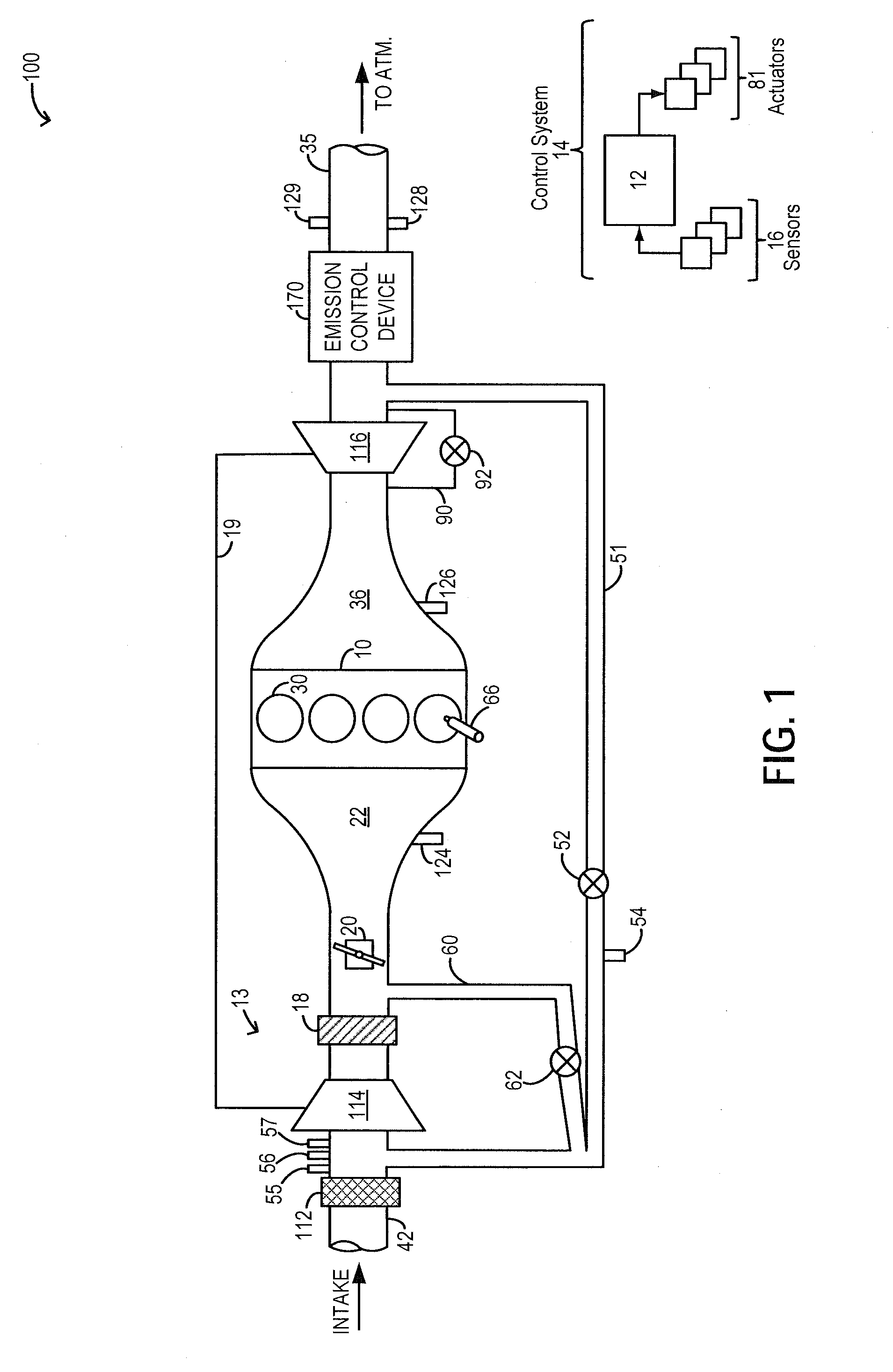
[0016]The following description relates to systems and methods for adjusting a proportion of compressed aircharge recirculated to a compressor inlet in a boosted engine system, such as the system of FIG. 1, from downstream of a charge air cooler. A controller may be configured to perform a control routine, such as the routine of FIG. 5, to adjust the amount of cooled compressed aircharge recirculated from downstream of the charge air cooler relative to the amount of EGR based on surge and condensation considerations. Therein, the controller may adjust the amounts based on a compressor inlet temperature and further based on EGR so that a temperature and humidity of an aircharge entering the compressor is maintained above a threshold where condensation can occur. The controller may also adjust the amounts based on an indication of compressor surge to improve a margin to the surge limit. As elaborated at FIG. 5, the controller may select between using increased hot EGR or increased rec...


PUM


Abstract

Methods and systems are provided for managing a compressor temperature using EGR to address surge and condensation. A variable mixture of cooled compressor recirculation flow and hot EGR is provided to a compressor inlet. A composition of the mixture is adjusted to maintain a compressor inlet temperature sufficiently warm so as to reduce ingestion of condensation, and a compressor outlet temperature sufficiently cold to be within component temperature limits with flow above the surge limit.

Description

FIELD[0001]The present application relates to methods and systems for coordinating compressor recirculation flow and EGR to improve boost control.BACKGROUND AND SUMMARY[0002]Engine systems may be configured with a boosting device, such as a turbocharger, for providing a boosted aircharge and improving peak power outputs. Therein a turbine is rotated using energy from an exhaust flow, the turbine then driving a compressor which delivers a boosted aircharge to the engine intake. In an effort to meet stringent federal government fuel economy standards, engine systems may also be configured with exhaust gas recirculation (EGR) systems wherein at least a portion of the exhaust gas is recirculated to the engine intake. For example, the EGR system may be a low-pressure EGR system (LP-EGR) that recirculates exhaust gas from downstream of an exhaust turbine to upstream of an exhaust compressor. EGR benefits include an increase in engine dilution, decrease in exhaust emissions, and improvemen...

Claims


Application Information

Patent Timeline
Patent Type & Authority Patents(United States)
IPC IPC(8): F02B33/44F02M25/07F02D23/00F02D41/00F02B29/04
CPCF02M25/07F02D41/0007F02D41/0065F02M25/0709F02M25/0751F02M25/0754F02M25/071F02D2200/0418F02M25/0728F02B29/0437F02D2041/0067F02M26/06F02M26/07F02M26/25F02M26/44F02M26/47Y02T10/12Y02T10/40
Inventor ULREY, JOSEPH NORMANBUCKLAND, JULIA HELEN
Owner FORD GLOBAL TECH LLC
Why Eureka
Try Eureka