Methods and systems for surge control

a surge control and surge technology, applied in mechanical control, electric control, combustion engines, etc., can solve problems such as potential surge, reduced forward flow through compressors, and prone to surge, and achieve the effect of improving consumer satisfaction

Active Publication Date: 2017-11-14
FORD GLOBAL TECH LLC
View PDF10 Cites 3 Cited by
  • Summary
  • Abstract
  • Description
  • Claims
  • Application Information

AI Technical Summary

Benefits of technology

[0002]Engine systems may be configured with boosting devices, such as turbochargers or superchargers, for providing a boosted aircharge and improving peak power outputs. The use of a compressor allows a smaller displacement engine to provide as much power as a larger displacement engine, but with additional fuel economy benefits. However, compressors are prone to surge. For example, when an operator tips-out of an accelerator pedal, an engine intake throttle closes, leading to reduced forward flow through the compressor, and a potential for surge. As such, surge can lead to NVH issues such as undesirable noise from the engine intake system, in addition to causing drivability and performance concerns. For example, during hard surge, the compressor allows air to momentarily backflow through the compressor resulting in rapid, high amplitude oscillations, while during soft surge, smaller pressure oscillations are experienced.
[0005]However the inventors herein have identified potential issues that may arise during surge line calibration. Specifically, surge lines that are calibrated to reduce soft surge and tip-in whoosh may result in torque loss. As an example, a surge line that is calibrated to avoid the soft surge region and / or the tip-in whoosh region may result in a compressor operating point where there is insufficient turbine power available to create boost. As such, this may result in torque loss. For example, if a CCRV is opened to keep the operating point of a compressor from crossing to the left of an aggressively calibrated surge line, boost pressure and engine torque output may fall short of the torque demanded at the tip-in. This can reduce vehicle performance and degrade vehicle drivability.
[0006]In one example, the above issue may be addressed by a method for a boosted engine, comprising: adapting a surge line of a compressor map during vehicle operation as a function of vehicle speed. In this way, tip-in whoosh can be addressed without losing boosted engine performance at the tip-in.
[0008]In this way, a compressor surge line may be calibrated as a function of vehicle speed in order to take advantage of vehicle noise at higher vehicle speed conditions to mask whoosh noise while prioritizing NVH mitigation at lower vehicle speeds. Consequently, it may be possible to provide the technical result of achieving a balanced trade-off between drivability and NVH reduction, thereby improving consumer satisfaction in a wide range of operating conditions.

Problems solved by technology

However, compressors are prone to surge.
For example, when an operator tips-out of an accelerator pedal, an engine intake throttle closes, leading to reduced forward flow through the compressor, and a potential for surge.
As such, surge can lead to NVH issues such as undesirable noise from the engine intake system, in addition to causing drivability and performance concerns.
If the operating point of the compressor moves to the left of a “surge line”, hard surge occurs.
While soft surge is characterized by small amplitude oscillations in pressure and flow during steady-state conditions, when large enough, the soft surge oscillations can also lead to audible NVH and / or drivability concerns.
However the inventors herein have identified potential issues that may arise during surge line calibration.
Specifically, surge lines that are calibrated to reduce soft surge and tip-in whoosh may result in torque loss.
As an example, a surge line that is calibrated to avoid the soft surge region and / or the tip-in whoosh region may result in a compressor operating point where there is insufficient turbine power available to create boost.
As such, this may result in torque loss.
For example, if a CCRV is opened to keep the operating point of a compressor from crossing to the left of an aggressively calibrated surge line, boost pressure and engine torque output may fall short of the torque demanded at the tip-in.
This can reduce vehicle performance and degrade vehicle drivability.
At lower vehicle speeds below the threshold vehicle speed, road and wind noise may not be sufficient to mask turbo whoosh noise.

Method used


Image

  • Methods and systems for surge control
  • Methods and systems for surge control
  • Methods and systems for surge control

Examples


Embodiment Construction

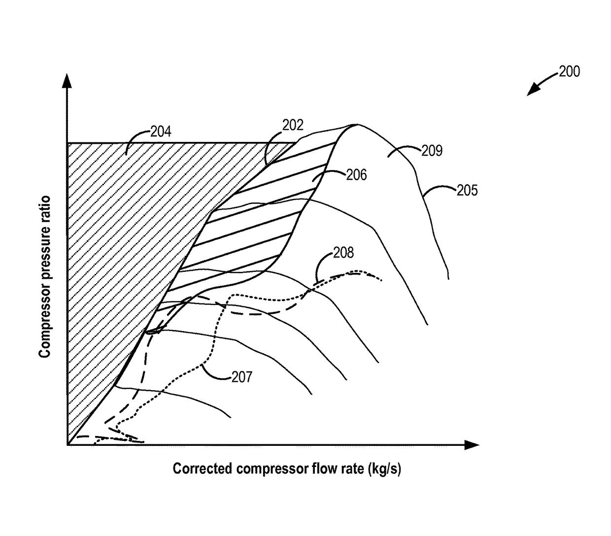
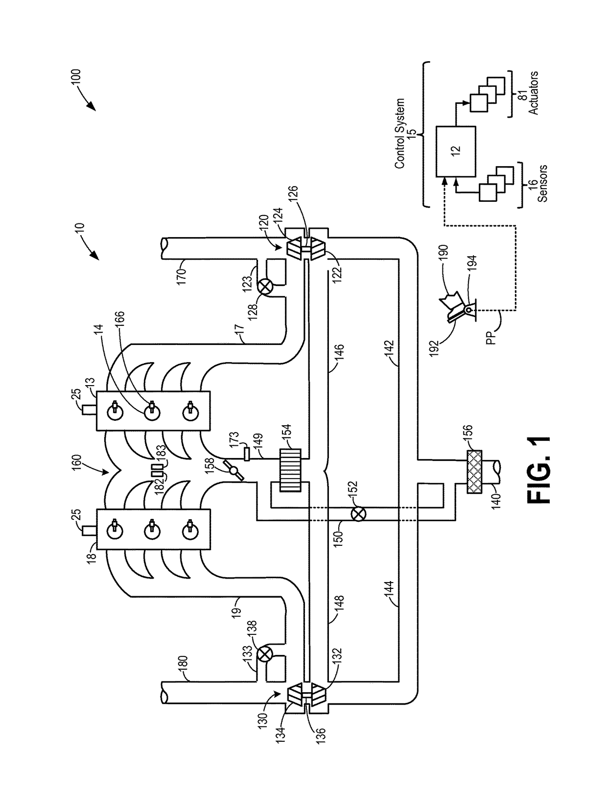
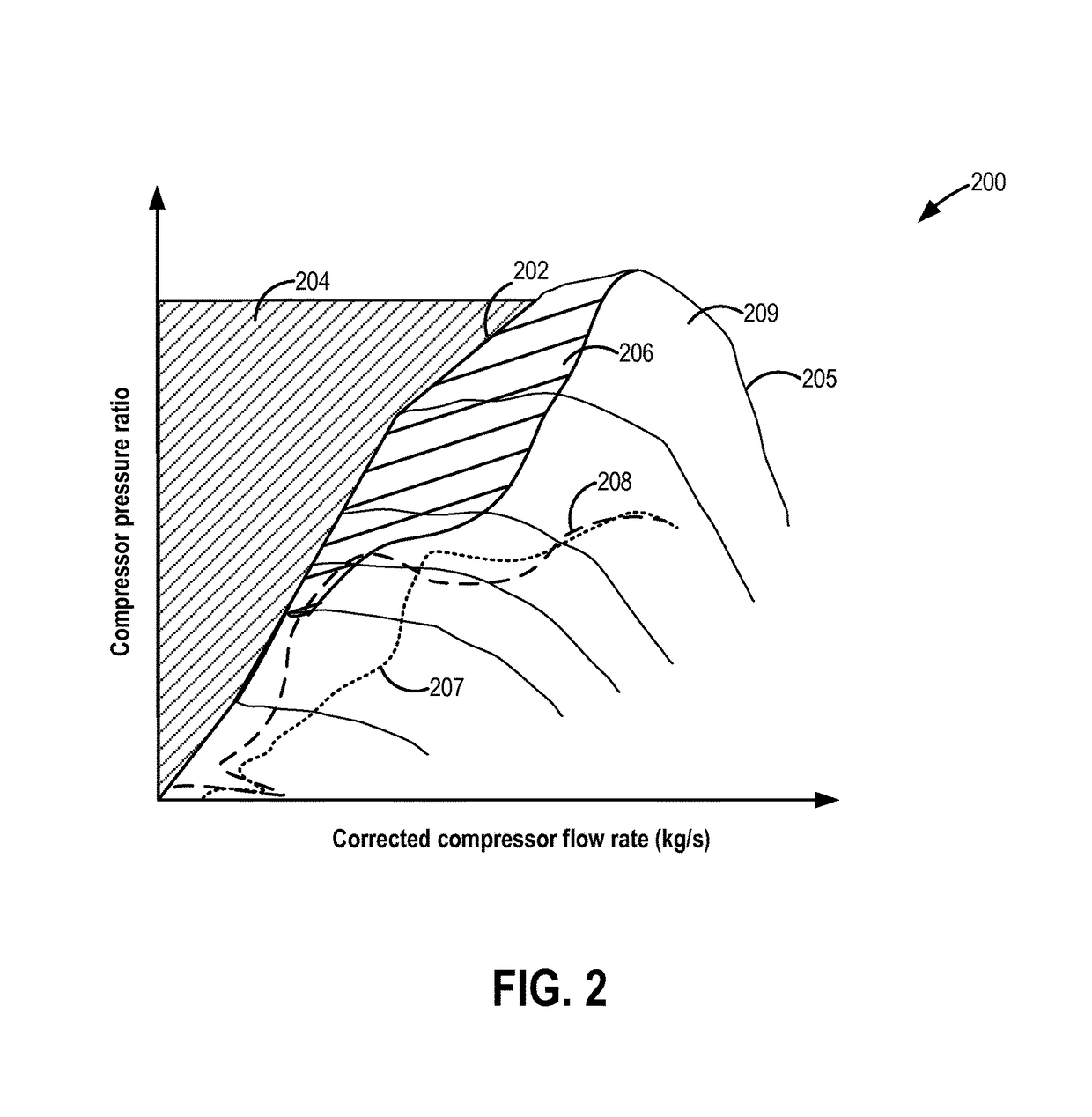
[0021]The following description relates to systems and methods for calibrating a surge line of a compressor map (such as the map shown in FIG. 2) for a compressor included in a boosted engine system, such as the system of FIG. 1. For example, drivability may be reduced when the surge line is calibrated aggressively to avoid compressor operation in soft surge regions for noise vibration and harshness (NVH) reduction as illustrated in FIGS. 3-4B. In order to obtain a balanced tradeoff between drivability and NVH mitigation, a controller may be configured to perform a control routine, such as the routines of FIGS. 6A-7 to adjust calibration of the surge line based on vehicle speed and / or engine speed in addition to compressor pressure ratio. Further, the controller may adjust the calibration according to the method of FIGS. 5A-5C to determine a final surge line of the compressor based on vehicle speed and / or engine speed. Example calibration of surge line based on vehicle and / or engine...


PUM


Abstract

Methods and systems are provided for calibrating a compressor surge line. In one example, a method may include adjusting the compressor surge line based on a vehicle speed in addition to a compressor pressure ratio. For example, at higher vehicle speeds, above a threshold vehicle speed, a less aggressive surge line calibration may be utilized in order to improve drivability while at lower vehicle speeds, below the threshold vehicle speed, a more aggressive surge line calibration may be utilized for NVH mitigation.

Description

FIELD[0001]The present application relates to methods and systems for adapting a surge line calibration in engine systems configured with a continuously variable compressor recirculation valve to improve surge control.BACKGROUND AND SUMMARY[0002]Engine systems may be configured with boosting devices, such as turbochargers or superchargers, for providing a boosted aircharge and improving peak power outputs. The use of a compressor allows a smaller displacement engine to provide as much power as a larger displacement engine, but with additional fuel economy benefits. However, compressors are prone to surge. For example, when an operator tips-out of an accelerator pedal, an engine intake throttle closes, leading to reduced forward flow through the compressor, and a potential for surge. As such, surge can lead to NVH issues such as undesirable noise from the engine intake system, in addition to causing drivability and performance concerns. For example, during hard surge, the compressor ...

Claims


Application Information

Patent Timeline
Patent Type & Authority Patents(United States)
IPC IPC(8): F02D41/22F02D41/00F02D41/24
CPCF02D41/0007F02D41/22F02D41/2464F02D41/2422Y02T10/144F02D2200/501F02B37/16F02B37/162F02D29/02F02D2200/101F02D2700/07Y02T10/12
Inventor JANKOVIC, MRDJAN J.BUCKLAND, JULIA HELENOSSAREH, HAMID-REZATENG, CHARLIE
Owner FORD GLOBAL TECH LLC
Why Eureka
Try Eureka