

Methods and systems for boost control
a boost control and boost technology, applied in the direction of charge feed system, combustion engine, non-fuel substance addition to fuel, etc., can solve the problems of increasing the risk of condensation at both the compressor inlet and the charge air cooler outlet, damage to the blades, introduction of water into the engine, etc., to improve fuel economy, improve peak power output, and increase engine dilution
- Summary
- Abstract
- Description
- Claims
- Application Information
AI Technical Summary
Benefits of technology
Problems solved by technology
Method used
Image

Examples
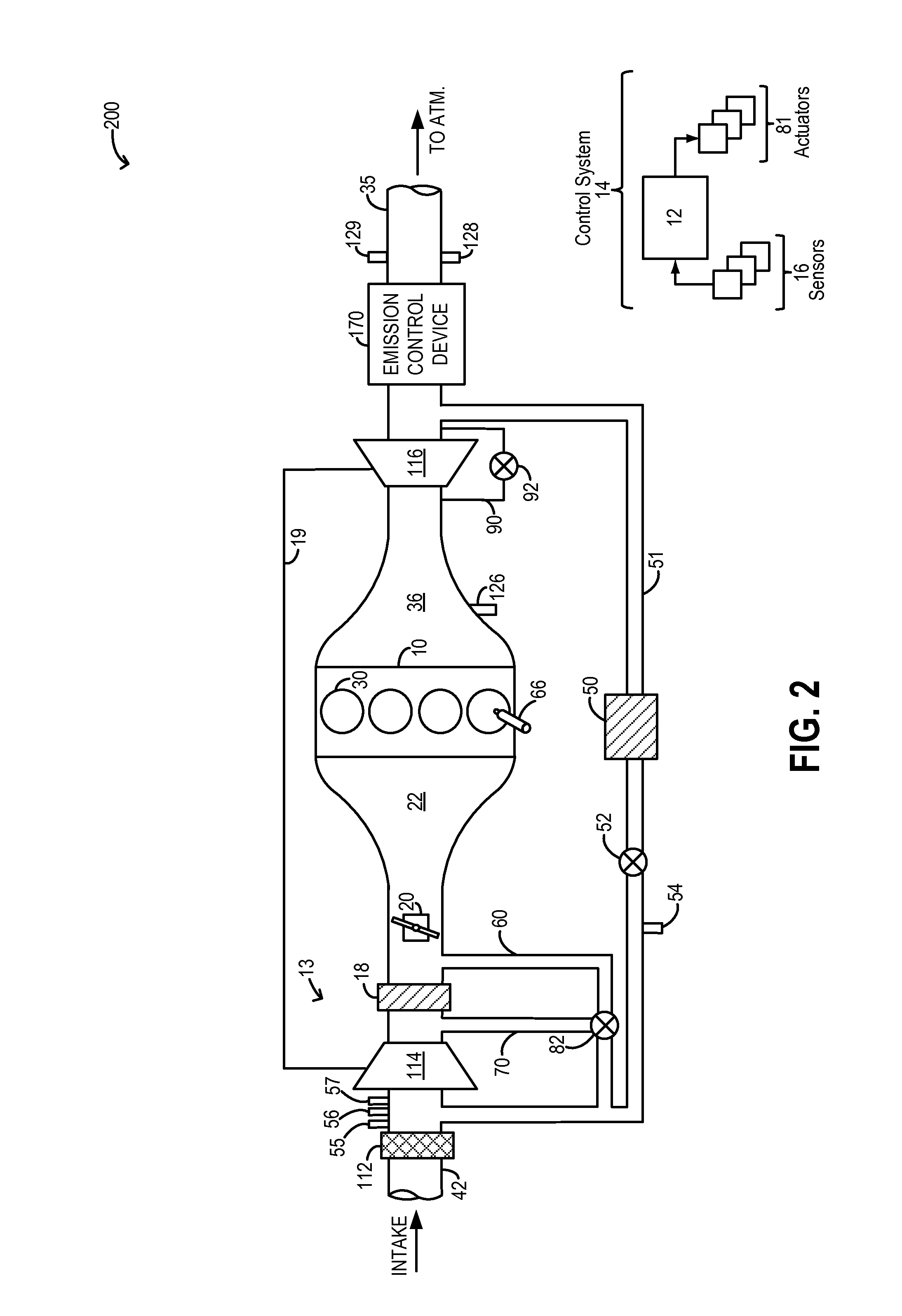
embodiment 200
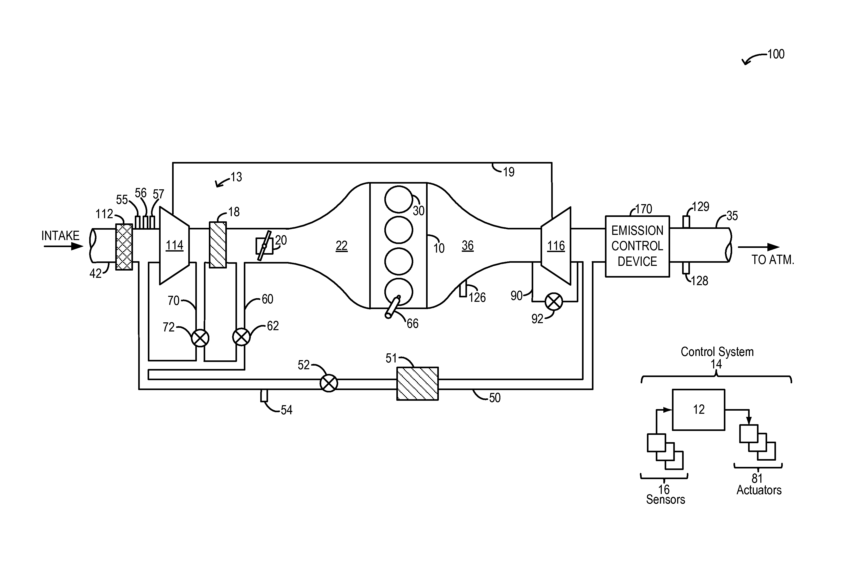
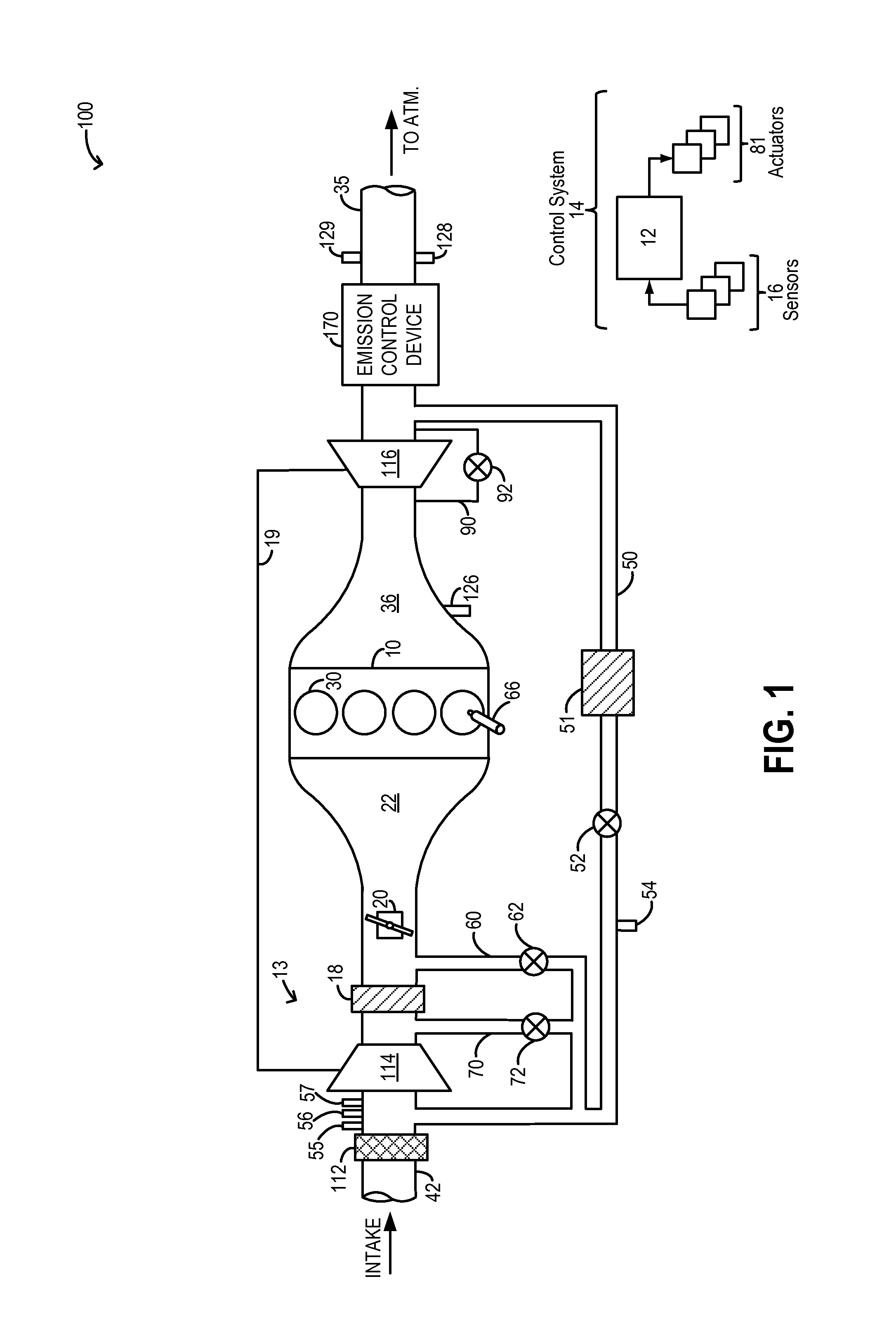
[0023]One or more valves may be coupled to the recirculation passages to control an amount of flow recirculated to the compressor inlet. In one example embodiment, depicted at FIG. 1, the first passage may include a first valve 62 for adjusting an amount of cooler recirculation flow recirculated to the compressor inlet while the second passage may include a second valve 72 for adjusting an amount of warmer recirculation flow recirculated to the compressor inlet. In an alternate embodiment 200, as depicted at FIG. 2, flow through the first and second passages may be controlled by a common valve 82. Common valve 82 may be an on-off type single variable valve for controlling flow along the first and second passages. Alternatively, common valve 82 may be a thermostat-controlled proportioning valve that is configured to adjust an amount of flow received at the compressor inlet from the first and second passages to provide a temperature-controlled recirculation flow mixture at the compres...
embodiment 800
[0037]It will be appreciated that while the embodiments of FIGS. 1-2 show two distinct compressor recirculation flow passages, in still other embodiments, only one flow passage may be provided. For example, as shown in embodiment 800 of FIG. 8, the engine system may be configured with a single compressor recirculation passage 60 including compressor recirculation valve 62 for recirculating cooled compressed air from downstream of charge air cooler 18 to the inlet of compressor 114. Therein, in response to an indication of surge, the controller may open (e.g., fully open) valve 62 to recirculate compressed air from downstream of the charge air cooler and upstream of the intake throttle to the compressor inlet. By addressing surge with only cooled compressed air, that is compressed aircharge that has been cooled upon passing through the charge air cooler, a temperature amplification effect of recirculation flow is reduced. In addition, by locating the compressor bypass system post the...
PUM
 Abstract
Description
Claims
Application Information