Evap canister purge prediction for engine fuel and air control

a technology of engine fuel and air control, applied in the direction of electric control, combustion-air/fuel-air treatment, instruments, etc., can solve the problems of feedback control, no data for ecm, and ineffective exhaust emissions control

Active Publication Date: 2005-10-27
GM GLOBAL TECH OPERATIONS LLC
View PDF12 Cites 33 Cited by
  • Summary
  • Abstract
  • Description
  • Claims
  • Application Information

AI Technical Summary

Benefits of technology

[0007] The present invention provides a method and an apparatus for controlling the engine air and fuel ratio during purging of an evaporative vapor storage canister. The apparatus includes a controller programmed to use a calculation to estimate the amount of hydrocarbon and air in purge vapor from an evaporative vapor storage canister to reduce the amount of metered fuel and air entering the engine.
[0010] The invention further provides a method for purging a vapor storage canister having adsorbed fuel (or hydrocarbon) vapor coupled with an engine having a system for controlling the amount of fuel provided to the engine, e.g. an electronic engine control module. In the method, the amount of fuel vapor and air in the purge is estimated using an estimate or determination of initial concentration of hydrocarbon vapor in the purge an equation that predicts the decrease with time of the amount of hydrocarbon in the purge from the evaporative vapor storage canister. The equation is preferably based on Langmuir adsorption isotherm equations. An initial concentration of hydrocarbon vapor in the purge air may be measured or estimated based on known factors such as engine temperature, time since refueling, seasonal RVP of the fuel, and the adsorption capacity and quantity of the adsorbent in the evaporative vapor storage canister. An ECM or PCM uses the calculation of fuel vapor flow from the canister during purging to improve fuel efficiency and / or reduce exhaust emissions. The amount of fuel drawn from the fuel tank and / or intake air can be reduced by the known amount of fuel vapor and air in the purge stream.

Problems solved by technology

Presently, however, canister purge fuel and air are not metered, and so the ECM has no data to use in adjusting the fuel and air to the engine.
Feedback control, as it is after the fact, is not very effective in exhaust emissions control.
On the other hand, more stringent evap emissions regulations require increased purge air rates, meaning even more un-metered air entering the engine.
This approach will result in feed forward control that is very effective in exhaust emission control, but would require adding an expensive purge sensor to the engine.

Method used


Image

  • Evap canister purge prediction for engine fuel and air control
  • Evap canister purge prediction for engine fuel and air control
  • Evap canister purge prediction for engine fuel and air control

Examples


Embodiment Construction

[0018] The following description of the preferred embodiment(s) is merely exemplary in nature and is in no way intended to limit the invention, its application, or uses.

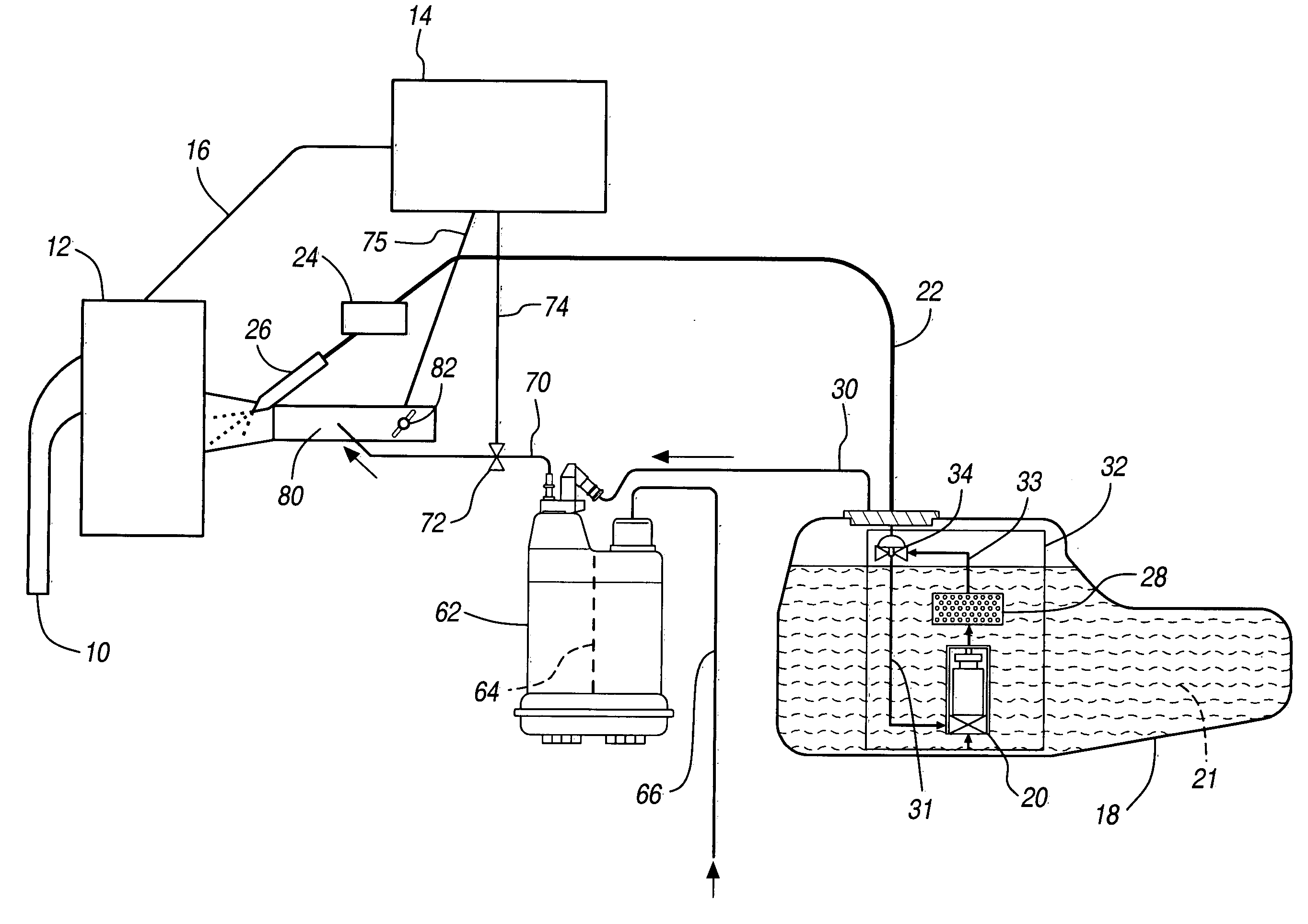
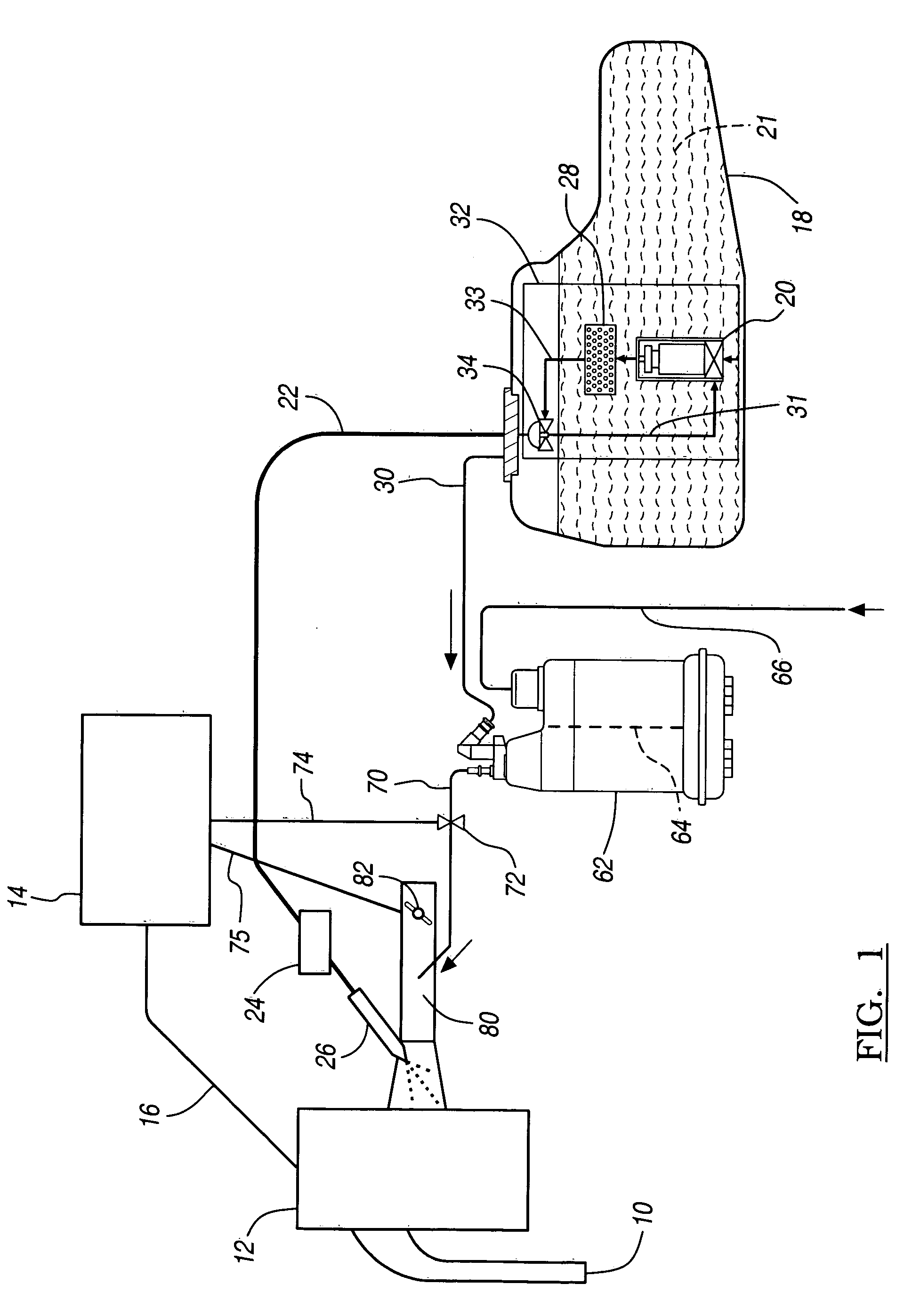
[0019] Referring now to FIG. 1, an engine 12 having an intake manifold 80 and exhaust manifold 10 is illustrated. The vehicle may be a conventional (non-hybrid) vehicle including an internal combustion engine or a hybrid vehicle including an internal combustion engine and an electric motor (not shown). The engine 12 is preferably an internal combustion engine that is controlled by a controller 14. The engine 12 typically burns gasoline, ethanol, and other volatile hydrocarbon-based fuels. The controller 14 may be a separate controller or may form part of an engine control module (ECM), a powertrain control module (PCM), or another vehicle controller.

[0020] When the engine 12 is started, the controller 14 receives signals from one or more engine sensors, transmission control devices, and / or emissions control devices...


PUM


Abstract

In a system and a method for purging a vapor storage canister having adsorbed fuel vapor (or hydrocarbon vapor) by drawing air through the storage canister the storage canister being coupled with an engine having a system for controlling the amount of fuel provided to the engine, the amount of fuel vapor in the purge is estimated using a model that predicts fuel vapor concentration in the purge vapor. The engine controller uses the estimated amount of fuel vapor and air brought into the engine from the evaporative vapor storage canister for better control of engine air and fuel during purging.

Description

FIELD OF THE INVENTION [0001] The present invention relates generally to systems and methods connected with vapor storage canisters. In particular, the present invention concerns estimating hydrocarbon vapor and air drawn into an engine from purge of an evap canister and using the estimate for engine air and fuel control. BACKGROUND OF THE INVENTION [0002] The automotive industry has actively sought improved emissions reduction, including reduction in emissions due to gasoline evaporation. Gasoline includes a mixture of hydrocarbons ranging from higher volatility butanes (C4) to lower volatility C8 to C10 hydrocarbons. When vapor pressure increases in the fuel tank due to conditions such as higher ambient temperature or displacement of vapor during filling of the tank, fuel vapor flows through openings in the fuel tank. To prevent fuel vapor loss into the atmosphere, the fuel tank is vented into a canister called an “evap canister” that contains an adsorbent material such as activat...

Claims


Application Information

Patent Timeline
Patent Type & Authority Applications(United States)
IPC IPC(8): F02D41/00F02M25/08F02M37/10
CPCF02D41/0042F02D41/0045F02M37/106F02M25/089F02D2041/1433F02D41/00F02M25/08F02D45/00
Inventor REDDY, SAM R.
Owner GM GLOBAL TECH OPERATIONS LLC
Why Eureka
Try Eureka