Sewer cleaning method

a technology for cleaning and sludge, applied in the direction of cleaning process and equipment, chemistry apparatus and processes, etc., can solve the problems of reducing flow, increasing manufacturing costs, and unable to achieve proper material flow and flushing water, so as to maximize the cleaning effect and maintain the level of liquid. high

Inactive Publication Date: 2011-12-22
BAZIUK SLAWKO MORRIS
View PDF25 Cites 9 Cited by
  • Summary
  • Abstract
  • Description
  • Claims
  • Application Information

AI Technical Summary

Benefits of technology

[0018]In this way the cable or pulling element has only a small diameter less than that of supply hose so that it does not interfere with the cleaning of the pipe. The hose system supplying the cleaning liquid to the second head is pulled behind the head in the cleaned pipe so that it does not interfere with the movement of the movement of the second head in the pipe or the movement of the solids and liquid in the pipe in front of the second head.
[0019]In the third step the hose supply system can include a plurality of hoses for supplying a high quantity of liquid. As these hoses are pulled behind the second head the number and bulk of the additional hoses does not interfere with the cleaning action. In this way the level of liquid can be maintained very high to provide the best cleaning action.
[0020]As the second cleaning head is designed without necessity for considering the function of carrying the head through the pipe in the first step, it allows the design to be arranged which maximizes the cleaning effect.

Problems solved by technology

This arrangement is disadvantageous in that the nozzles are carried on the lobes and therefore can be engaged into the material at the base of the pipe thus reducing flow.
This arrangement is relatively complex and bulky so that the cost of manufacture is increased and the proper flow of material and flushing water may not be achieved.
This arrangement is impractical in view of the difficulty of running along the length of the pipe which can have obstructions, bends and the like.

Method used


Image

  • Sewer cleaning method
  • Sewer cleaning method
  • Sewer cleaning method

Examples


Embodiment Construction

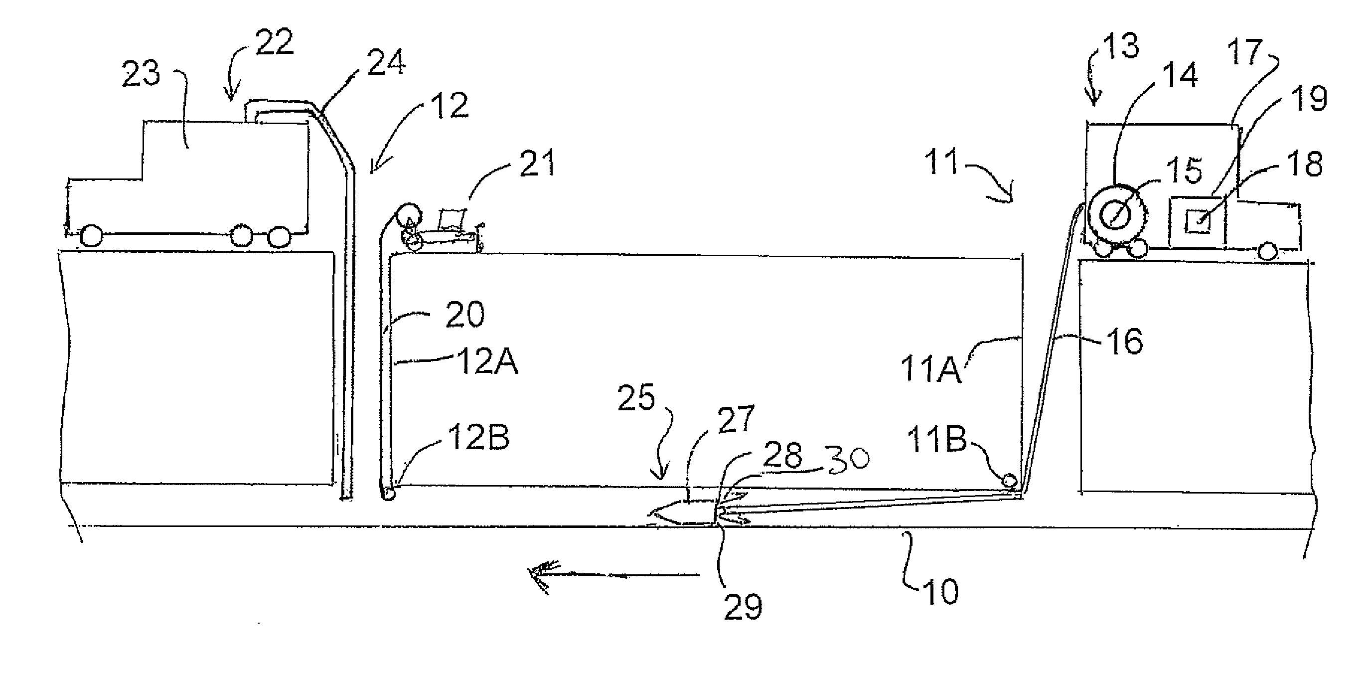
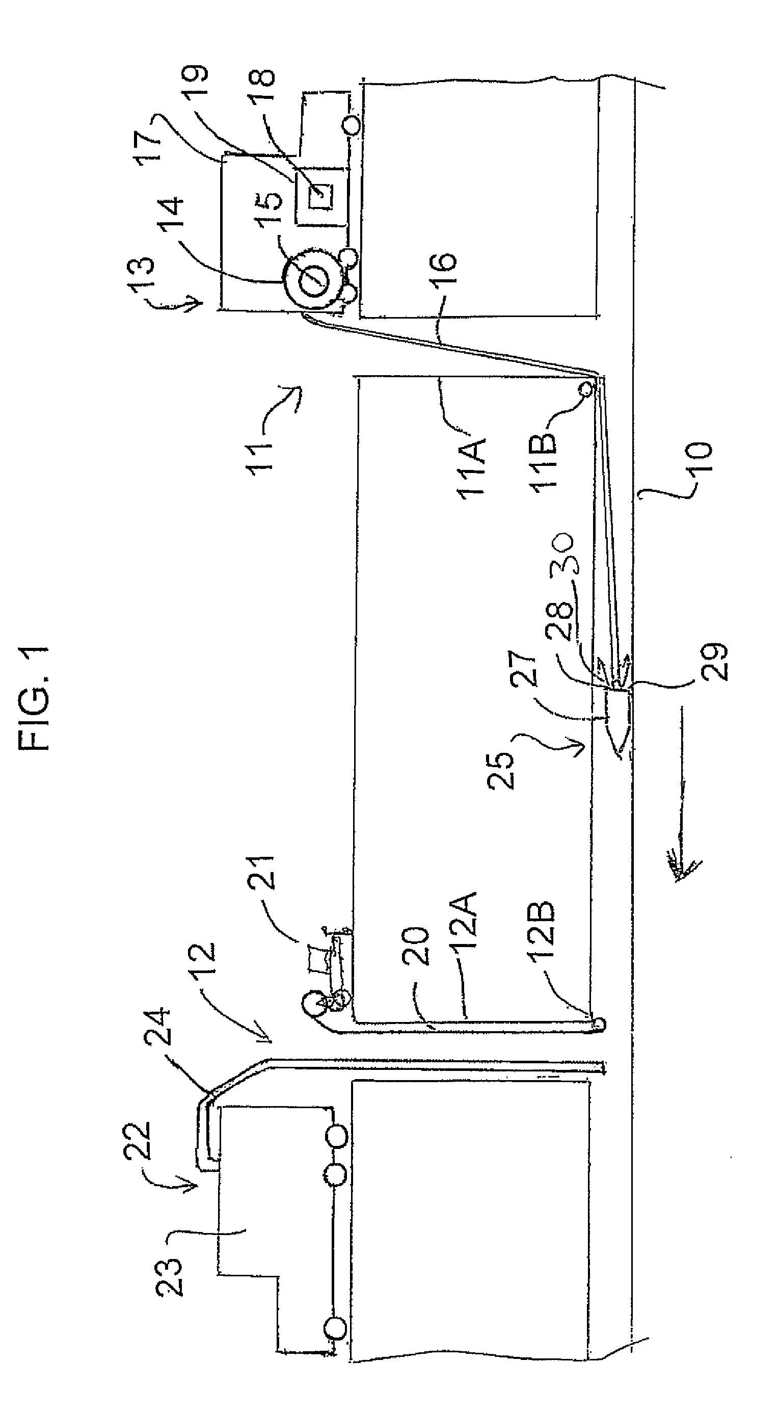
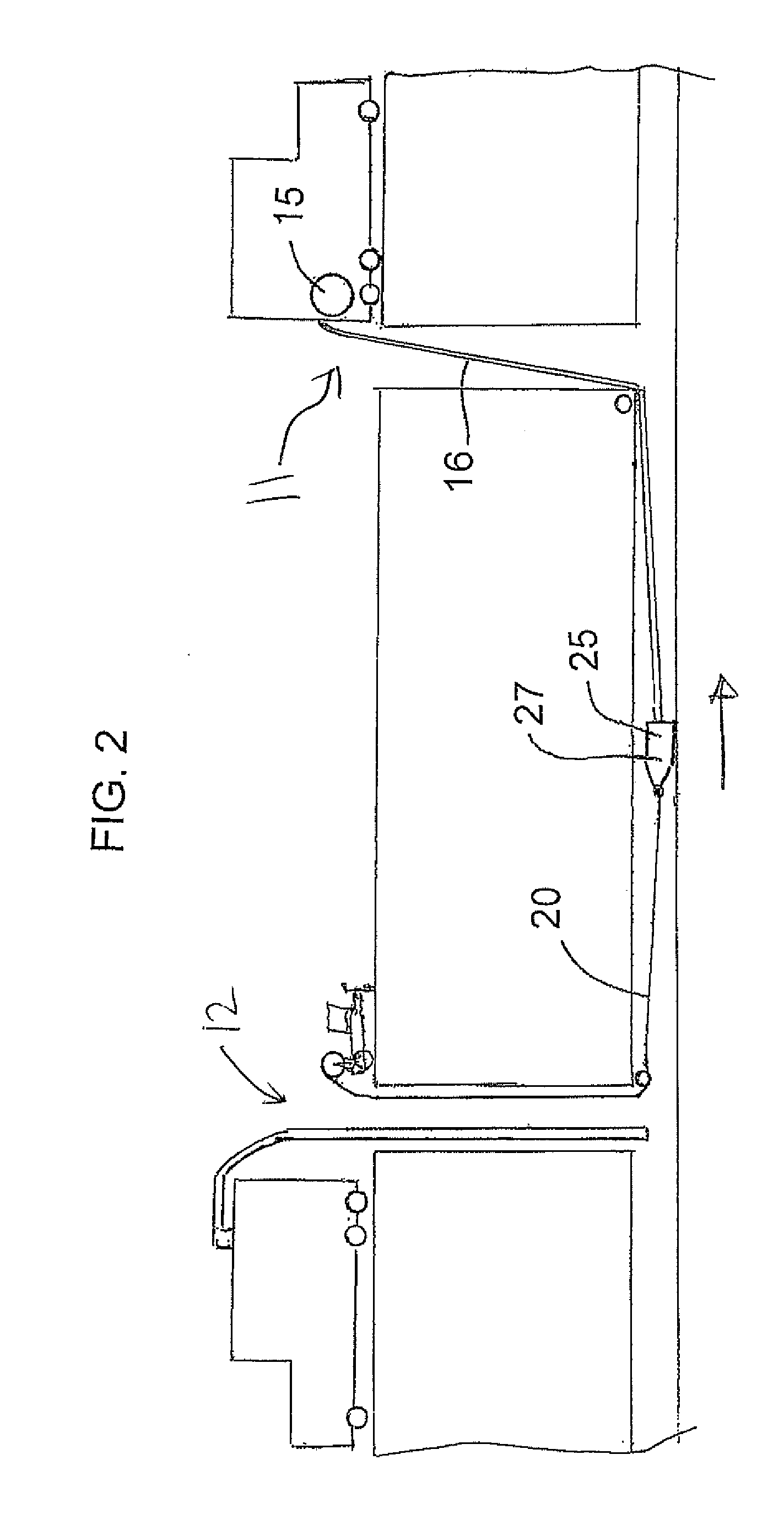
[0025]A method for cleaning a sewer pipe of collected solid materials using an apparatus designed for the method is shown in FIGS. 1 to 3.

[0026]The method is used with a pipe 10 to be cleaned of collected debris including sand, gravel, sticks and other material which can enter such pipes add tends to settle along the length of the pipe. Such pipes for use with the method described herein are typically of a large diameter, greater than 24 inches since such pipes are much more difficult to clean so that the method described provides an enhanced cleaning action. However there is no limit on the size of pipe to be cleaned.

[0027]Access to the pipe is provided at a first location 11 and at a second longitudinally spaced location 12. These are typically pre-constructed openings with vertical access to the ground and are spaced along the pipe at convenient intervals to grant suitable access for cleaning, repair and inspection.

[0028]At the first location 11 is provided a hose system 13 inclu...


PUM


Abstract

A sewer pipe is cleaned of collected solids by providing a water supply hose at a first location on the pipe and by driving a jet nozzle head to a second location along the pipe using jets directed along the pipe. At the second location the head is changed for a second head attached to a cable and is pulled back to the first location by the hose. The nozzle is then pulled back to the second location by pulling the cable while nozzles directed along the pipe toward the second location drive the solids forwardly to the second location for extraction.

Description

[0001]This invention relates to a method for cleaning sewer drains using a jet nozzle system which carries collected solids to a discharge points for extraction.BACKGROUND OF THE INVENTION[0002]Examples of systems of this type are shown in U.S. Pat. Nos. 4,699,163 and 5,720,309 (issued Feb. 24, 1998) both of the present inventor which includes an elongate pipe section having a rear end for connection to the hose and a forward end connected to a cylindrical housing. At a rear face of the housing is provided a plurality of rearwardly extending jets surrounding the pipe section. A plurality of skid bars are attached to the housing longitudinally of the housing at angularly spaced positions around the housing with those skid bars extending from the rear face of the housing rearwardly and inwardly for attachment to the pipe section.[0003]Further examples are shown in U.S. Pat. No. 3,380,461 (Maasberg), U.S. Pat. No. 3,678,948 (Hedges assigned to Rockwell Manufacturing Co.); U.S. Pat. No....

Claims


Application Information

Patent Timeline
Patent Type & Authority Applications(United States)
IPC IPC(8): B08B9/00
CPCB08B9/0433
Inventor BAZIUK, SLAWKO MORRIS
Owner BAZIUK SLAWKO MORRIS
Why Eureka
Try Eureka