Press-fetching type liquid suction bottle

A liquid and aspirator technology, which is applied in the field of push-and-take liquid suction bottles, can solve the problems of waste, time-consuming, and user inconvenience.

Inactive Publication Date: 2008-12-03
林翊强
View PDF0 Cites 7 Cited by
  • Summary
  • Abstract
  • Description
  • Claims
  • Application Information

AI Technical Summary

Problems solved by technology

Yet when the liquid in the bottle is used up gradually, because the residual liquid evenly spreads on the bottom surface of the bottle body, the liquid level may be lower than the lower end opening of the suction pipe 3 because the lower end opening of the suction pipe 3 cannot be close to the bottle body 1 On the bottom surface, once the liquid level drops below the opening of the suction tube 3, the residual liquid cannot be drawn any more. Some users may mistakenly believe that the liquid in the bottle is completely used up, and discard the suction bottle together w

Method used


Image

  • Press-fetching type liquid suction bottle
  • Press-fetching type liquid suction bottle
  • Press-fetching type liquid suction bottle

Examples


Embodiment Construction

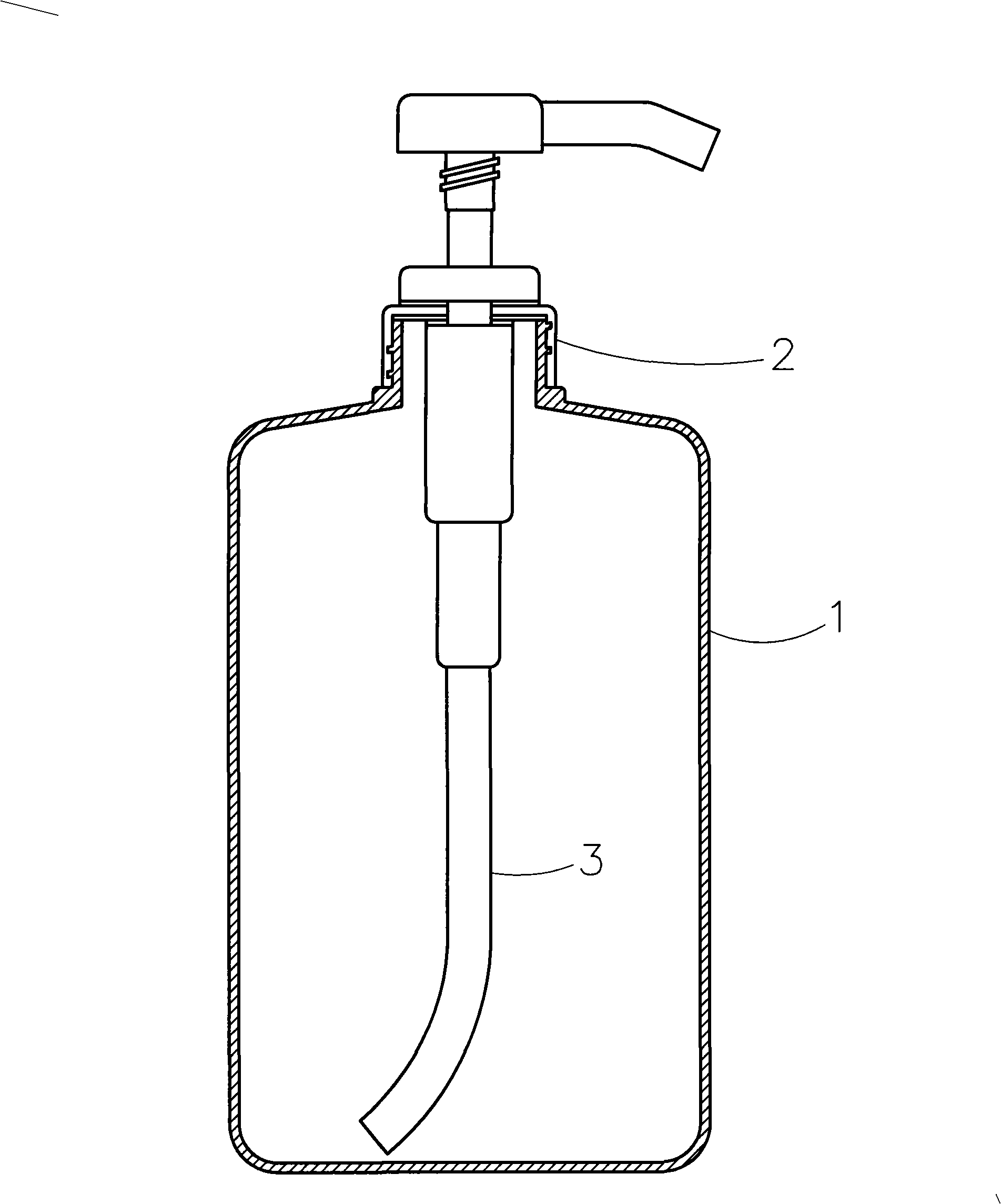
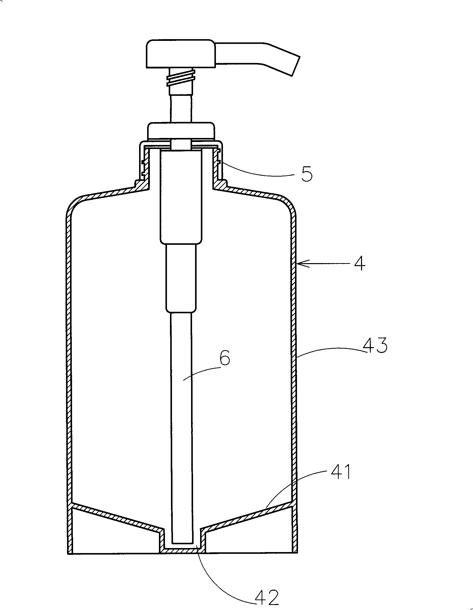
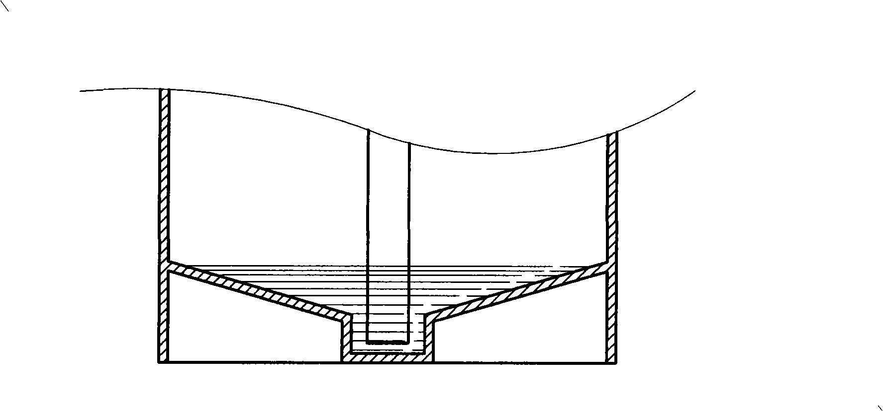
[0020] See first figure 2 , is a cross-sectional view of the present invention, and it can be seen that the pressure-taking type liquid suction bottle of the present invention is mainly composed of a bottle body 4, an aspirator 5 located at the mouth of the bottle, and a downward extension of the aspirator 5. Its basic principle and structure are all the same as those known in the art, but it is characterized in that the bottom surface 41 of the bottle body 4, the central part of the bottom surface 41 is a downwardly recessed container 42, and its notch is upward and parallel. Connecting the bottom surface 41, the diameter of the container 42 is slightly larger than the diameter of the straw 6, and the length of the straw 6 is just enough to extend into the container 42, and the bottom surface 41 of the bottle body 4 is downward from the side wall 43 of the bottle body 4. Extending obliquely to the notch of the container 42 , that is, the bottom surface 41 forms an inverted c...


PUM


Abstract

The invention relates to a pressed type liquid pumping bottle, in particular to a bottle body used for holding shampoo or shower gel and other dense liquid. A concave-down holding groove is molded in the central part of the bottom surface of the bottle body; the diameter of the holding groove is slightly greater than that of a straw extending from a bottle mouth pumping device downwards, so as to place the straw in the holding grove; the bottom surface around the holding groove extends upwards to the side of the bottle body in an inclined state. When a small amount of residual liquid is left inside the bottle body, the liquid can flow into the holding groove along the inclined bottom surface, thereby providing convenience for pumping the last residual liquid.

Description

technical field [0001] The present invention relates to liquid holding bottles, in particular to pressure-taking liquid suction bottles. Background technique [0002] The pressure-taking liquid suction bottle is widely used in daily life, especially for absorbing thick liquids, such as shampoo, shower gel and facial cleanser, etc. Its structure is as follows figure 1 As shown, it is mainly composed of an upright cylindrical bottle body 1, an aspirator 2 installed at the bottle mouth above the bottle body 1, and a suction pipe 3 extending downward from the aspirator 2 to the bottom surface of the bottle body 1 As a result, when the aspirator 2 is pressed, the liquid contained in the bottle can be drawn out of the bottle through the suction tube 3 . Yet when the liquid in the bottle is used up gradually, because the residual liquid evenly spreads on the bottom surface of the bottle body, the liquid level may be lower than the lower end opening of the suction pipe 3 because th...

Claims


Application Information

Patent Timeline
IPC IPC(8): B65D83/00B65D83/14B65D83/38B65D25/38B65D47/34
Inventor 林翊强
Owner 林翊强
Why Eureka
Try Eureka