Liquid crystal projection system

a projection system and liquid crystal technology, applied in the field of projection systems, can solve the problems of unnecessary waste of energy, and achieve the effects of uniform luminance, small transmission rate, and large transmission ra

Inactive Publication Date: 2006-05-25
PRODISC TECH INC
View PDF4 Cites 7 Cited by
  • Summary
  • Abstract
  • Description
  • Claims
  • Application Information

AI Technical Summary

Benefits of technology

[0013] As mentioned above, the liquid crystal projection system of the invention utilizes the gradient filter device having the central area with a smaller transmission rate and the edge area with a larger transmission rate. Thus, after the light beam outputted from the light source passes through the gradient filter devices of the imager units, the luminance of the central area is smaller while the luminance of the edge area is higher so that the illumination light beam with the non-uniform luminance may be produced. Consequently, the phenomenon of the non-uniform image luminance caused by the unequal projection distances of the light beams projected on the imager units may be improved, and the image with uniform luminance may be obtained. Furthermore, it is unnecessary to waste the energy to pre-compensate the luminance. So, the gray level of the liquid crystal projection system may be increased, and the final image quality may be enhanced.

Problems solved by technology

Furthermore, it is unnecessary to waste the energy to pre-compensate the luminance.

Method used


Image

  • Liquid crystal projection system
  • Liquid crystal projection system
  • Liquid crystal projection system

Examples


first embodiment

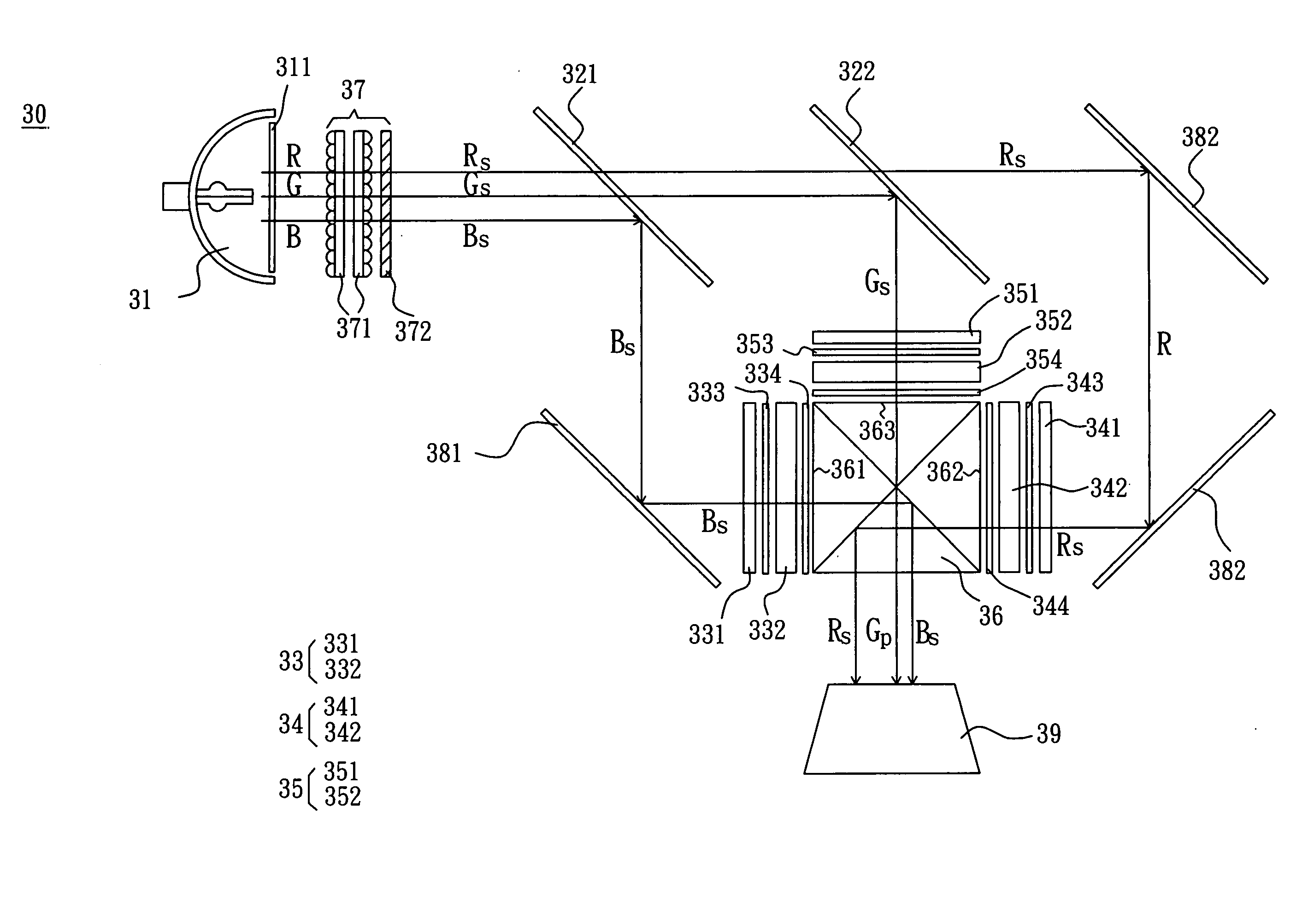
[0022] Referring to FIG. 3, a liquid crystal projection system 30 according to the first embodiment of the invention includes at least one light source 31, a first dichroic mirror 321, a second dichroic mirror 322, a first imager unit 33, a second imager unit 34, a third imager unit 35, and a prism unit 36. In this embodiment, the liquid crystal projection system 30 is applied in a transmittive liquid crystal projector.

[0023] The light source 31 emits a light beam, which forms a light route. In this embodiment, the light source 31 may be a lamp, an organic light-emitting diode (OLED), an organic light-emitting diode array (OLED array), a laser and a laser array. In addition, an ultra-violet / infrared cut-off filter 311 adjacent to the light source 31 filters the ultra-violet ray and infrared ray of the light beam.

[0024] In this embodiment, the liquid crystal projection system 30 further includes a first polarization beam splitter unit 37 disposed at a side of the light source 31. T...

second embodiment

[0036] Referring to FIG. 6, a liquid crystal projection system 40 includes a light source 41, a first dichroic mirror.421, a second dichroic mirror 422, a first imager unit 43, a second imager unit 44, a third imager unit 45 and a prism unit 46. In this embodiment, the liquid crystal projection system 40 is applied in a reflective liquid crystal projector (such as a LCoS Projector).

[0037] The light source 41 emits a light beam that forms a light route. An ultra-violet / infrared cut-off filter 411 adjacent to the light source 41 filters the ultra-violet ray and infrared ray of the light beam. The features and functions of the light source 41, ultra-violet / infrared cut-off filter 411 and prism unit 46 of this embodiment are the same as those of the light source 31, ultra-violet / infrared cut-off filter 311 and prism unit 36 of the first embodiment, so the detailed descriptions are omitted for concise purpose.

[0038] In this embodiment, the liquid crystal projection system 40 further in...


PUM

PropertyMeasurementUnit
transmission rateaaaaaaaaaa
transparentaaaaaaaaaa
dielectricaaaaaaaaaa

Abstract

A liquid crystal projection system includes a prism unit, a first imager unit, a second imager unit, a third imager unit, at least one light source, a first dichroic mirror and a second dichroic mirror. The first, second and third imager units are disposed at first, second and third sides of the prism unit, respectively. The first, second and third imager units respectively have first, second and third gradient filter devices. The light source emits a light beam forming a light route. The first dichroic mirror is disposed on the light route and adjacent to the light source. The second dichroic mirror is disposed on the light route. At least part of the light beam is transmitted to the first dichroic mirror and then to the second dichroic mirror. A transmission rate of a central area of each gradient filter device is smaller than that of an edge area.

Description

BACKGROUND OF THE INVENTION [0001] 1. Field of Invention [0002] The invention relates to a projection system, and more particularly to a liquid crystal projection system. [0003] 2. Related Art [0004] Recently, the liquid crystal display devices, such as the direct view monitors for the LCD monitors, the notebook computers and the digital liquid crystal televisions, and the in-direct view display panels, such as the LCoS Panel (Liquid Crystal on Silicon Panel), the HTPS-LCD (High Temperature Polysilicon Liquid Crystal Display) and the likes, for the monitors of the liquid crystal projectors, rear-projection televisions, and the likes, have been gradually and widely used in the daily life. Because the direct view monitor still has many limitations in the large-scale display, the liquid crystal projector and the rear-projection television, each of which has the large-scale display and uses the in-direct view display panel having high resolution in conjunction with an optical engine, ha...

Claims


Application Information

Patent Timeline
Patent Type & Authority Applications(United States)
IPC IPC(8): G02F1/1335
CPCG02F1/133509G02F2203/30H04N9/3152
Inventor LIANG, NAI-YUEH
Owner PRODISC TECH INC
Why Eureka
Try Eureka