Method for carrying out slurry bed reaction

A slurry bed and reaction technology, applied in the chemical industry, can solve problems such as back-mixing, high slip velocity of gas and slurry, and influence on reaction efficiency

Active Publication Date: 2014-08-06
SHANGHAI ADVANCED RES INST CHINESE ACADEMY OF SCI +3
View PDF15 Cites 7 Cited by
  • Summary
  • Abstract
  • Description
  • Claims
  • Application Information

AI Technical Summary

Problems solved by technology

On the other hand, for the devices developed in the prior art, if operating at a higher gas flow rate, the relative slip veloci

Method used


Image

  • Method for carrying out slurry bed reaction
  • Method for carrying out slurry bed reaction
  • Method for carrying out slurry bed reaction

Examples


Embodiment 1

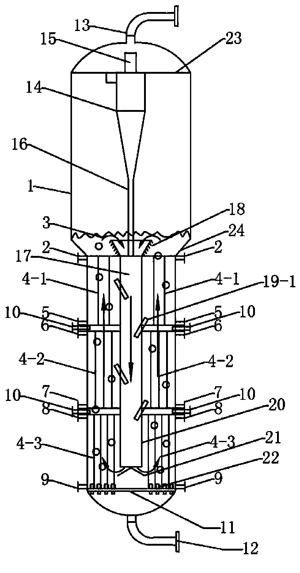
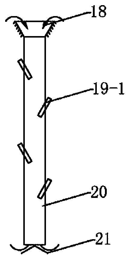
[0082] This example uses figure 1 The reactor shown is for Fischer-Tropsch synthesis. The inner diameter of the slurry bed stainless steel reactor shell is 1.2 meters, and the axial height of the reactor is 35 meters. liquid separator. The liquid level of the slurry bed is located 18 meters above the syngas distributor. The upper edge of the expansion port at the top of the draft tube is located at a height of 14.5 meters above the syngas distributor, the bottom of the feeding tube of the draft tube is located at a height of 0.2 meters above the syngas distribution plate, and the inner diameter of the feeding tube 20 of the draft tube 17 is 0.36 m. Meter.

[0083] The draft tube is completely submerged below the liquid level of the slurry bed, and the outer surface of the expansion port at the upper end of the draft tube 17 includes six rows of ring-shaped raised structures. The height of these ring-shaped raised structures is 0.25 meters, and the included angle with the axi...

Embodiment 2

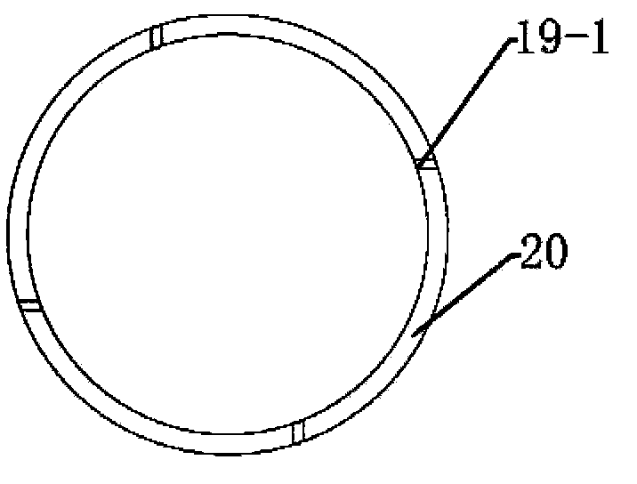
[0089] Embodiment 2: use the same reaction device as in Example 1, but the difference is that, as shown in Figure 8 (b), the following changes have been made to the arrangement of the nozzles in the draft tube: 8 nozzles are divided into two layers and arranged , the vertical distance between the two layers is 4 meters, and each layer is provided with 4 nozzles, which are installed at 4 meters and 8 meters below the expansion section of the diversion pipe. These nozzles are evenly arranged around the circumference of the diversion pipe, and each nozzle The included angle between directions is 30°, and the arrangement of nozzles in the horizontal direction is still as shown in Figure 8(c), that is, the nozzle opening direction is along the tangential direction of the duct wall. The relevant experimental results are shown in Table 2.

Embodiment 3

[0090] Embodiment 3: The reactor setting method is the same as that of Example 1, the difference is that, in the top view, the nozzle is set in the manner shown in Figure 8(d), so that the opening of the nozzle is closer to the position in the middle of the draft tube, and the opening direction The angle between the nozzle and the tangential direction where the nozzle passes through the wall of the draft tube is about 60 degrees. This arrangement can prevent the jet from being hindered by the wall of the reactor. The relevant experimental results are shown in Table 2.


PUM


Abstract

The invention relates to a method for carrying out a slurry bed reaction. The method comprises that: a) a gaseous component is introduced into a slurry bed reactor to make the gaseous component rise, concurrently a slurry is driven to rise along with the rising gaseous component, and the gaseous component reacts in the slurry; b) the gaseous product of the reaction and the unreacted gaseous component rise and leave a slurry bed layer (3), at least a part of the slurry enters a diversion pipe (17) from the upper portion opening of the diversion pipe (17), flows downward along the diversion pipe (17), outflows from the lower portion outlet of the diversion pipe (17), and enters an annular space, and at least a spraying nozzle sprays the gas, the liquid or the slurry; and (c) the steps (a) and (b) are repeatedly performed. With the method, the mass transfer and the heat transfer in the slurry bed reaction system can be promoted.

Description

Technical field: [0001] The invention belongs to the field of chemical industry and relates to a method for performing slurry bed reaction. Background technique [0002] In the organic chemical synthesis process, the gas-liquid-solid three-phase reaction system containing gaseous, liquid and solid reaction materials is a very important system. For example, the slurry bed reactor for Fischer-Tropsch synthesis is an industrial application three-phase reactor. The Fischer-Tropsch synthesis process refers to the synthesis gas (CO+H 2 ) into hydrocarbons and small amounts of organic oxygenates, a chemical conversion process characterized by a strong exotherm. Initially, people tried to use fixed bed and fluidized bed reactors for Fischer-Tropsch reaction operation, but the heat transfer efficiency of these reactors is not ideal, which will bring great difficulties to the reaction control. For this reason, a novel slurry bed reactor has been developed. The characteristic of th...

Claims


Application Information

Patent Timeline
IPC IPC(8): B01J8/22C10G2/00
Inventor 孙予罕廖波刘小浩王小泉赵陆海波张小莽罗艳宁王江峰陈延李晋平刘斌王东飞安杰逻·阿莫里
Owner SHANGHAI ADVANCED RES INST CHINESE ACADEMY OF SCI
Why Eureka
Try Eureka