Image pickup optical system and image pickup apparatus using the same
an optical system and optical technology, applied in the field of image pickup optical system and image pickup apparatus using the same, can solve problems such as difficulty in obtaining sufficient performan
- Summary
- Abstract
- Description
- Claims
- Application Information
AI Technical Summary
Benefits of technology
Problems solved by technology
Method used
Image
Examples
example 1
[0167]
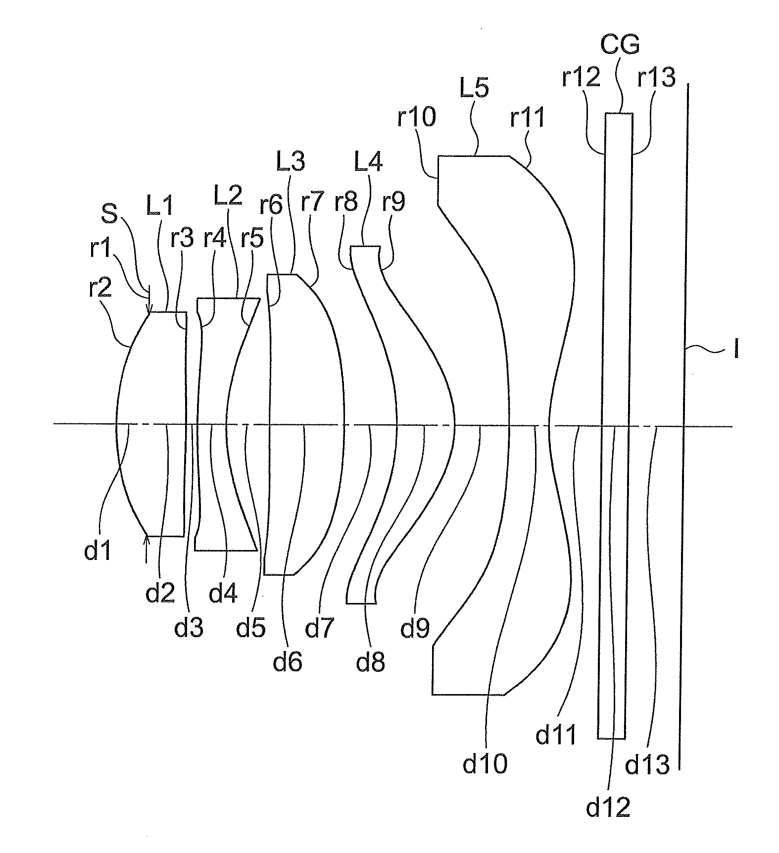
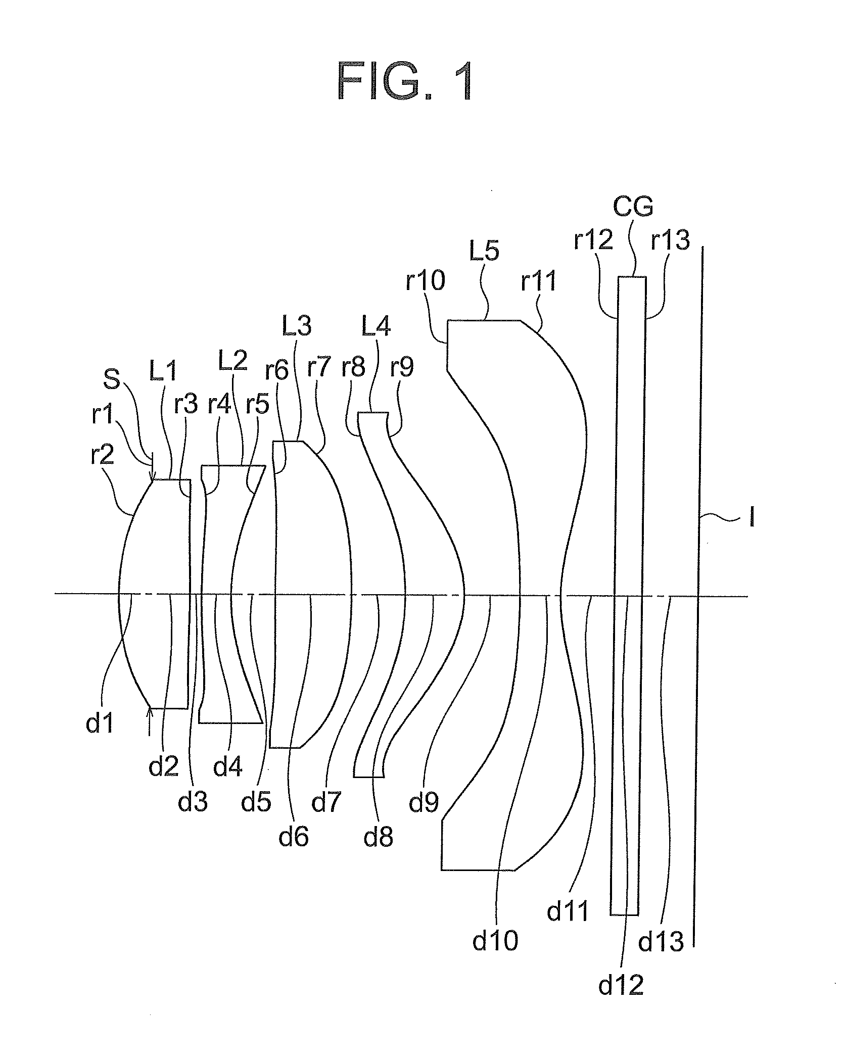
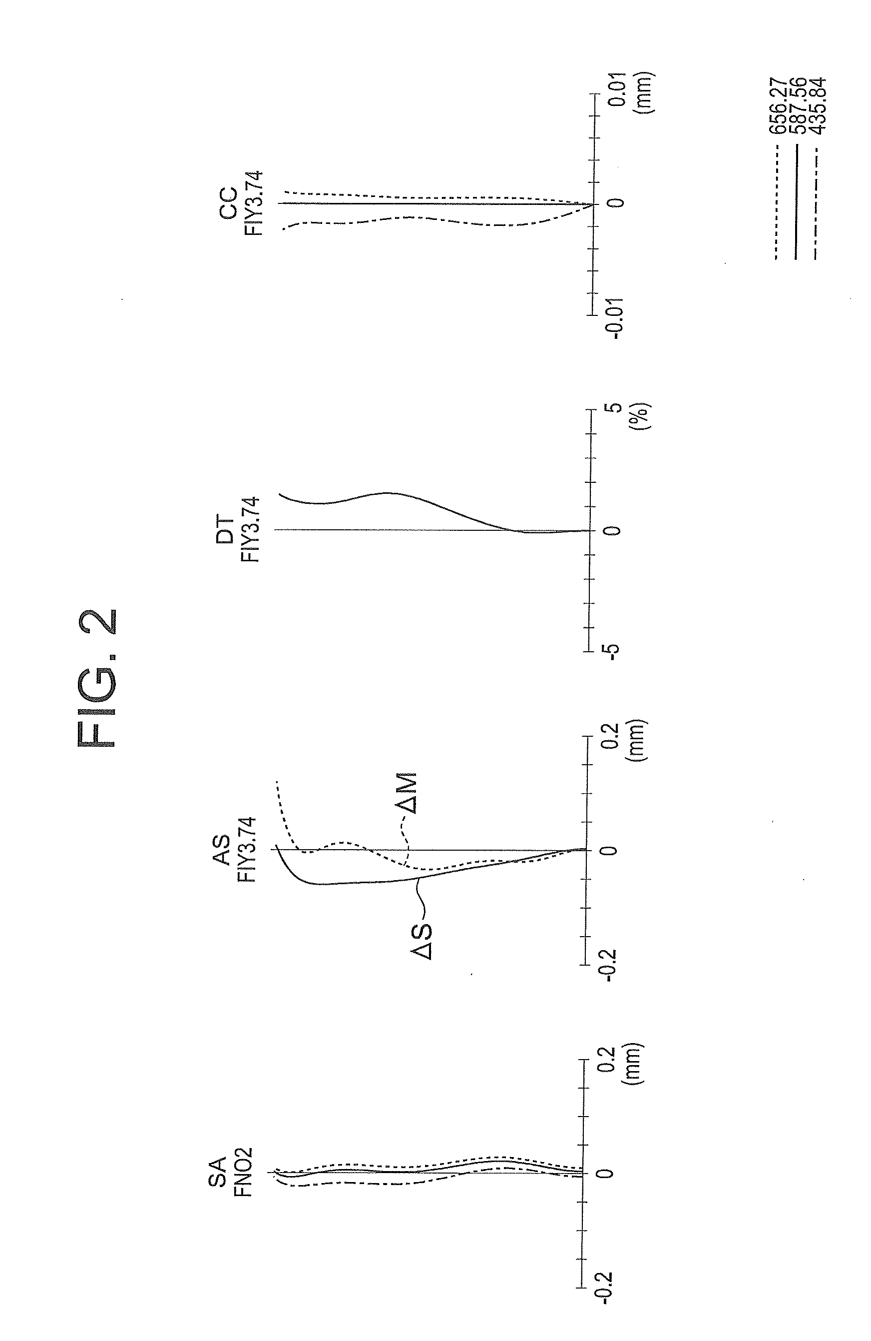
Unit mmSurface dataSurface no.rdndνdObject plane∞∞ 1(Stop)∞−0.35 2*2.4400.771.5336855.90 3*−10.4770.13 4*7.5050.321.6142025.59 5*2.0240.48 6*23.9140.831.5336855.90 7*−5.5860.58 8*−2.7230.641.5336855.90 9*−1.1960.6010*−7.6460.441.5336855.9011*1.9710.5812∞0.301.5163364.1413∞0.61Aspherical surface data2nd surfacek = −0.599A4 = 1.12317e−02, A6 = 3.48314e−03, A8 = 2.02768e−033rd surfacek = −576.615A4 = 1.24154e−02, A6 = 1.88361e−02, A8 = −1.31275e−024th surfacek = −10.712A4 = −1.53575e−02, A6 = 2.10836e−03, A8 = −7.90012e−03,A10 = −4.54582e−035th surfacek = 0.131A4 = −7.54593e−02, A6 = 4.52138e−02, A8 = −2.84244e−02,A10 = 5.59790e−036th surfacek = 0.000A4 = −2.24096e−02, A6 = −5.07084e−03, A8 = 6.52322e−03,A10 = −1.63989e−037th surfacek = 0.000A4 = −3.24487e−02, A6 = 1.44236e−02, A8 = −1.10883e−02,A10 = 1.77374e−038th surfacek = 0.919A4 = −3.67292e−02, A6 = 4.38769e−02, A8 = −1.35498e−02,A10 = 1.92171e−03, A12 = 2.23362e−059th surfacek = −1.230A4 = 3.10799e−02, A6 = −1.28481e−02, A...
example 2
[0168]
Unit mmSurface dataSurface no.rdndνdObject plane∞∞ 1(Stop)∞−0.31 2*2.6410.771.5336855.90 3*−6.9510.17 4*11.8910.321.6142025.59 5*2.0440.41 6*6.5520.771.5336855.90 7*−9.2190.52 8*−2.5860.751.5336855.90 9*−1.1780.5710*−6.2170.561.5336855.9011*2.0990.5812∞0.301.5163364.1413∞0.61Aspherical surface data2nd surfacek = −0.897A4 = 9.37088e−03, A6 = −1.00458e−03, A8 = 2.75896e−033rd surfacek = −160.384A4 = 1.74714e−02, A6 = −3.14751e−03, A8 = 3.62813e−034th surfacek = 34.466A4 = −1.09321e−02, A6 = 4.45947e−03, A8 = −4.64501e−03,A10 = 6.44346e−045th surfacek = 0.088A4 = −8.74463e−02, A6 = 5.09310e−02, A8 = −2.36496e−02,A10 = 3.95168e−036th surfacek = 0.000A4 = −3.03462e−02, A6 = −3.32371e−03, A8 = 4.95235e−03,A10 = −2.82618e−047th surfacek = 0.000A4 = −3.00710e−02, A6 = 1.58202e−02, A8 = −1.11251e−02,A10 = 2.58020e−038th surfacek = 0.770A4 = −3.12677e−02, A6 = 4.48383e−02, A8 = −1.24677e−02,A10 = 2.40034e−03, A12 = −1.87309e−049th surfacek = −1.402A4 = 2.39508e−02, A6 = −1.37276e−02, A8...
example 3
[0169]
Unit mmSurface dataSurface no.rdndνdObject plane∞∞ 1(Stop)∞−0.34 2*2.4680.781.5336855.90 3*−8.2070.16 4*14.4790.321.6142025.59 5*2.0490.43 6*5.7230.781.5336855.90 7*−10.7990.44 8*−2.6250.831.5336855.90 9*−1.2060.6810*−6.2310.431.5336855.9011*2.1100.5812∞0.301.5163364.1413∞0.58Aspherical surface data2nd surfacek = −0.606A4 = 1.16998e−02, A6 = −1.46368e−03, A8 = 3.86120e−033rd surfacek = −277.062A4 = 2.12171e−02, A6 = −4.10754e−03, A8 = 4.17051e−034th surfacek = 25.139A4 = −9.38778e−03, A6 = −2.43793e−04, A8 = −1.04062e−03,A10 = −1.11891e−035th surfacek = 0.292A4 = −9.01873e−02, A6 = 5.45676e−02, A8 = −2.55743e−02,A10 = 3.97760e−036th surfacek = 0.000A4 = −3.37340e−02, A6 = −2.73158e−03, A8 = 5.25322e−03,A10 = −5.22112e−047th surfacek = 0.000A4 = −3.29523e−02, A6 = 1.57911e−02, A8 = −1.04174e−02,A10 = 2.33750e−038th surfacek = 0.792A4 = −3.07059e−02, A6 = 4.56142e−02, A8 = −1.24436e−02,A10 = 2.25572e−03, A12 = −1.58094e−049th surfacek = −1.324A4 = 2.65702e−02, A6 = −1.34232e−02,...
PUM
 Abstract
Description
Claims
Application Information
 - R&D
- Intellectual Property
- Life Sciences
- Materials
- Tech Scout
- Unparalleled Data Quality
- Higher Quality Content
- 60% Fewer Hallucinations
Browse by: Latest US Patents, China's latest patents, Technical Efficacy Thesaurus, Application Domain, Technology Topic, Popular Technical Reports.
© 2025 PatSnap. All rights reserved.Legal|Privacy policy|Modern Slavery Act Transparency Statement|Sitemap|About US| Contact US: help@patsnap.com


