Antenna Selection with Frequency-Hopped Sounding Reference Signals

a frequency-hopped sounding and reference signal technology, applied in the direction of digital transmission, transmission path sub-channel allocation, wireless communication, etc., can solve the problems of increasing complexity exponentially, rf chain complexity, and relatively simple antennas

Active Publication Date: 2011-12-22
MITSUBISHI ELECTRIC RES LAB INC
View PDF11 Cites 23 Cited by
  • Summary
  • Abstract
  • Description
  • Claims
  • Application Information

AI Technical Summary

Problems solved by technology

However, processing the signals received in spatial multiplexing schemes, or with space-time trellis codes requires transceivers where the complexity can increase exponentially as a function of the number of antenna.
Antennas are relatively simple and cheap, while RF chains are considerably more complex and expensive.

Method used


Image

  • Antenna Selection with Frequency-Hopped Sounding Reference Signals
  • Antenna Selection with Frequency-Hopped Sounding Reference Signals
  • Antenna Selection with Frequency-Hopped Sounding Reference Signals

Examples


Embodiment Construction

[0052]Network Overview

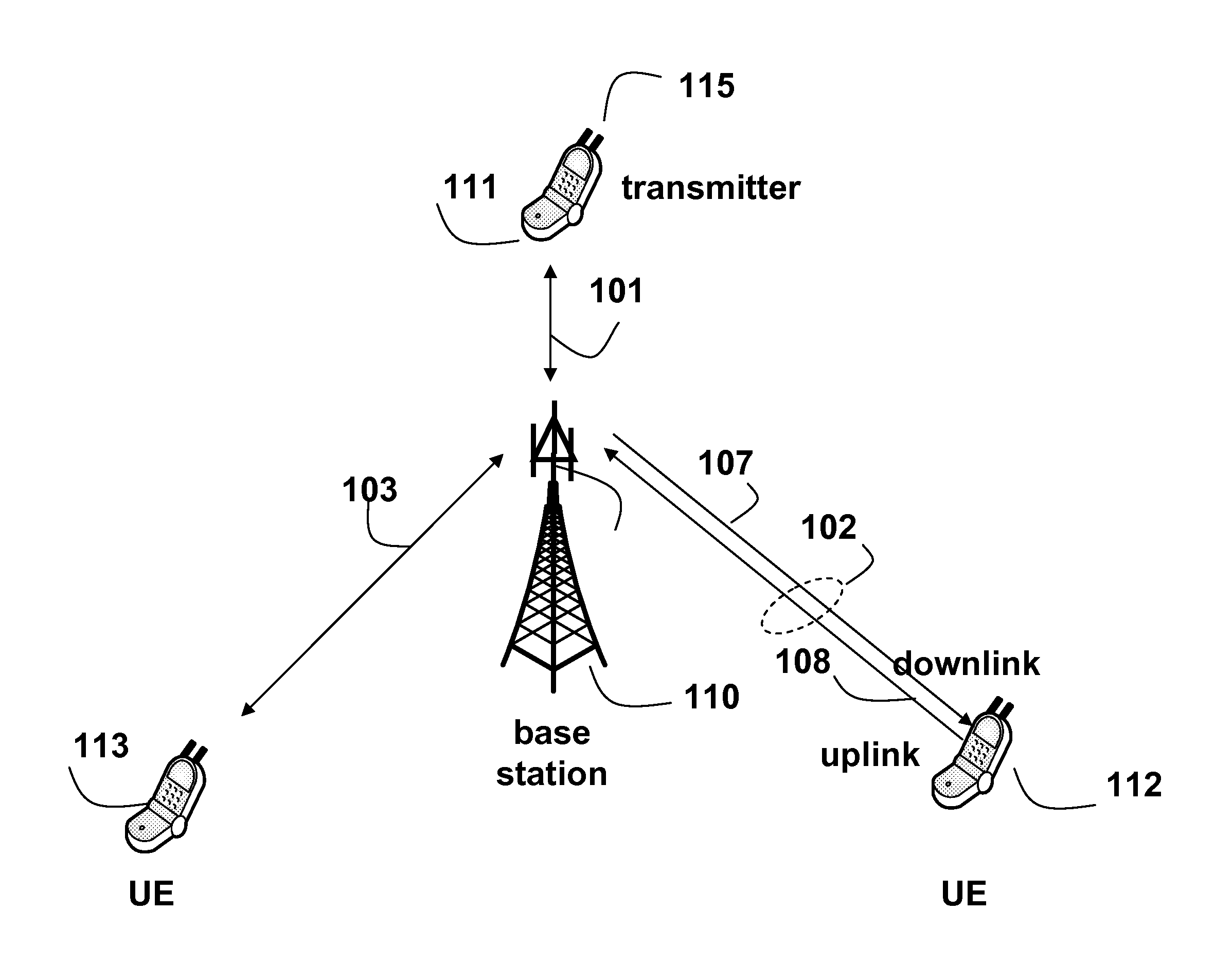
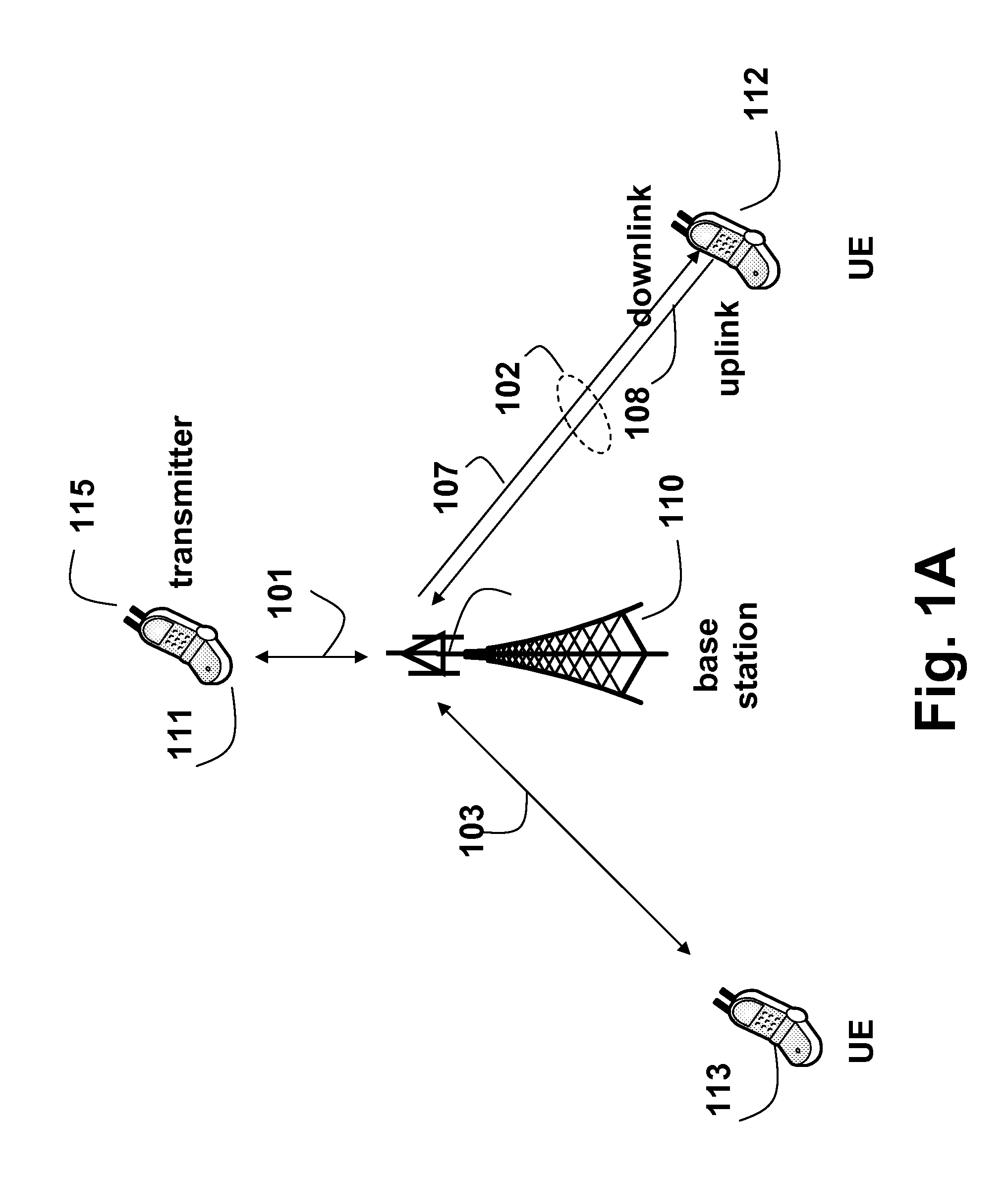
[0053]FIG. 1 shows a (general structure of a wireless network according to an embodiment of the invention. In one embodiment, the network operates according the 3GPP long term evolution standard (LTE). Multiple mobile user equipments (UEs) 111-113 communicate with a stationary base station (BS) 110. Each UE and the BS includes a transceiver.

[0054]The BS is called an evolved Node B (eNodeB) in the LTE standard. The BS manages and coordinates all communications with the UEs in a cell using wireless channels or connections 101, 102, 103. Each connection can operate as a downlink (DL) 107 from the BS station to the UE or as an uplink 108 from the UE to the BS. Because the transmission power available at the BS is orders of magnitude greater than the transmission power at the UE, the performance on the uplink is much more critical.

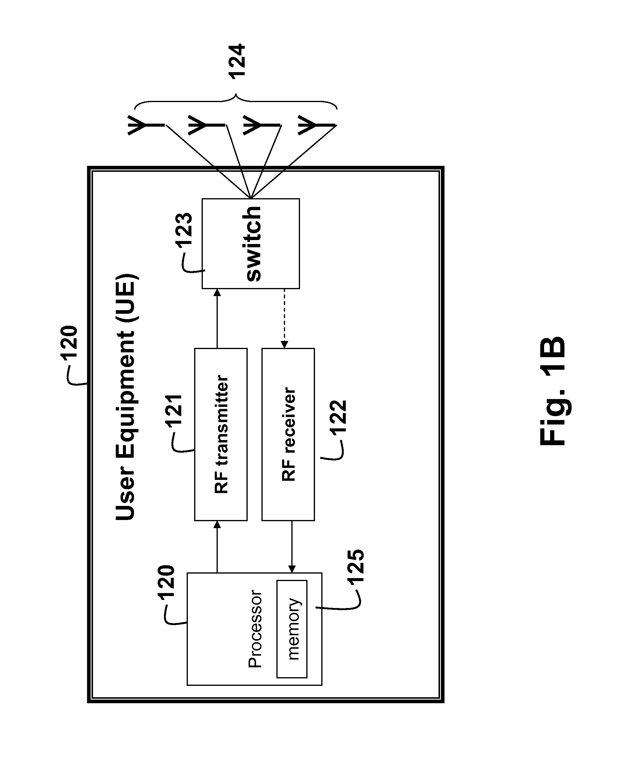
[0055]FIG. 1B is a block diagram of detail of UE 120. UE includes a processor for performing steps of the method described herein. The pr...


PUM


Abstract

The embodiments of the invention provide a method for selecting antennas for date transmission in a wireless communication network including user equipment (UE). The network is assigned a band of frequencies, wherein the band is partitioned into at least one set of subbands of the band according to a sounding reference signal (SRS) band-width configuration in a form of a code-tree having a plurality levels and each level is associated with a partition coefficient. The UE is configured to transmit frequency-hopped SRS on the set of sub-bands using subsets of the set of antennas. First, the method determines if a number of subbands in the set of the sub-bands is odd or even based on the SRS bandwidth configuration, and selects a particular subset of the antennas according to whether the number is odd or even. Then, the SRS is transmitted from the particular subset of the antennas.

Description

RELATED APPLICATIONS [0001]The following patent applications are related to the present application, and incorporated herein by reference:[0002]U.S. patent application Ser. No. 11 / 953,452, filed Dec. 10, 2007, entitled “Method and System for Generating Antenna Selection Signals in Wireless Networks;”[0003]U.S. patent application Ser. No. 12 / 055,522, filed Mar. 26, 2008, entitled “Method for Selecting Antennas in a Wireless Networks;”[0004]U.S. patent application Ser. No. 11 / 924,703, filed Oct. 26, 2007, entitled “Method for Implicit Selecting Antennas in a Wireless Networks;”[0005]U.S. patent application Ser. No. 11 / 834,345, filed Aug. 6, 2007, entitled “Method for Selecting Antennas in a Wireless Networks;”[0006]U.S. Provisional Patent Application No. 61 / 075,102, filed Jun. 24, 2008, entitled “Tree-Based Frequency-Hopped Sounding Reference Signals for Transmit Antenna Selection Training;”[0007]U.S. Provisional Patent Application No. 61 / 076,743, filed Jun. 30, 2008, entitled “Tree-B...

Claims


Application Information

Patent Timeline
Patent Type & Authority Applications(United States)
IPC IPC(8): H04B1/713
CPCH01Q1/246H01Q3/24H01Q25/00H04L5/0023H04L5/0048H04W88/08H04W88/02H04B1/713H04B7/0602H04L5/0053H04W28/16H04B7/0691
Inventor MEHTA, NEELESH B.TEO, KOON HOOZHANG, JINYUNVINOKUR, GENNADIY V.PUN, MAN-ON
Owner MITSUBISHI ELECTRIC RES LAB INC
Why Eureka
Try Eureka