Methods for manufacturing turbine components

a technology for turbine components and manufacturing methods, applied in the direction of turbines, machines/engines, mechanical equipment, etc., can solve the problems of high cost, long lead-time, and difficult fabrication of prior art methods, and achieve the effect of low yield, high cost and long lead-tim

Active Publication Date: 2011-12-22
HONEYWELL INT INC
View PDF5 Cites 161 Cited by
  • Summary
  • Abstract
  • Description
  • Claims
  • Application Information

AI Technical Summary

Benefits of technology

In accordance with an exemplary embodiment, a method is provided for manufacturing a turbine component from a turbine article formed with a high energy beam. The method includes encapsulating the turbine article with an encapsulation layer; and consolidating the turbine article.

Problems solved by technology

Given these considerations, turbine components may have relatively complex three-dimensional (3D) geometries that may raise difficult fabrication issues.
Such prior art methods are not only expensive and have long lead-times, but may additionally have low yields.
Development time and cost for certain turbine components may also be magnified because such components generally require several iterations.

Method used


Image

  • Methods for manufacturing turbine components
  • Methods for manufacturing turbine components
  • Methods for manufacturing turbine components

Examples


Embodiment Construction

The following detailed description is merely exemplary in nature and is not intended to limit the invention or the application and uses of the invention. Furthermore, there is no intention to be bound by any theory presented in the preceding background or the following detailed description.

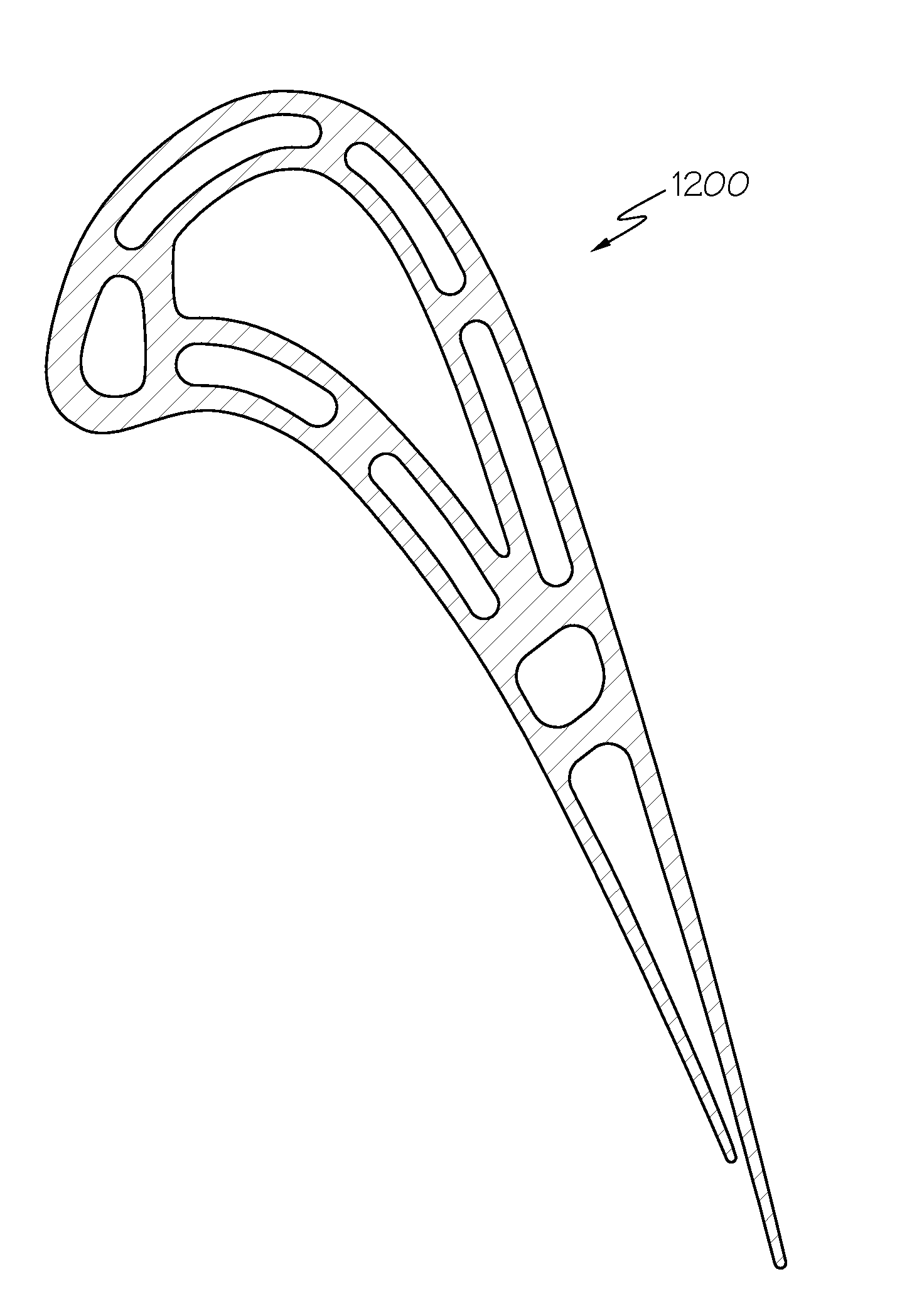
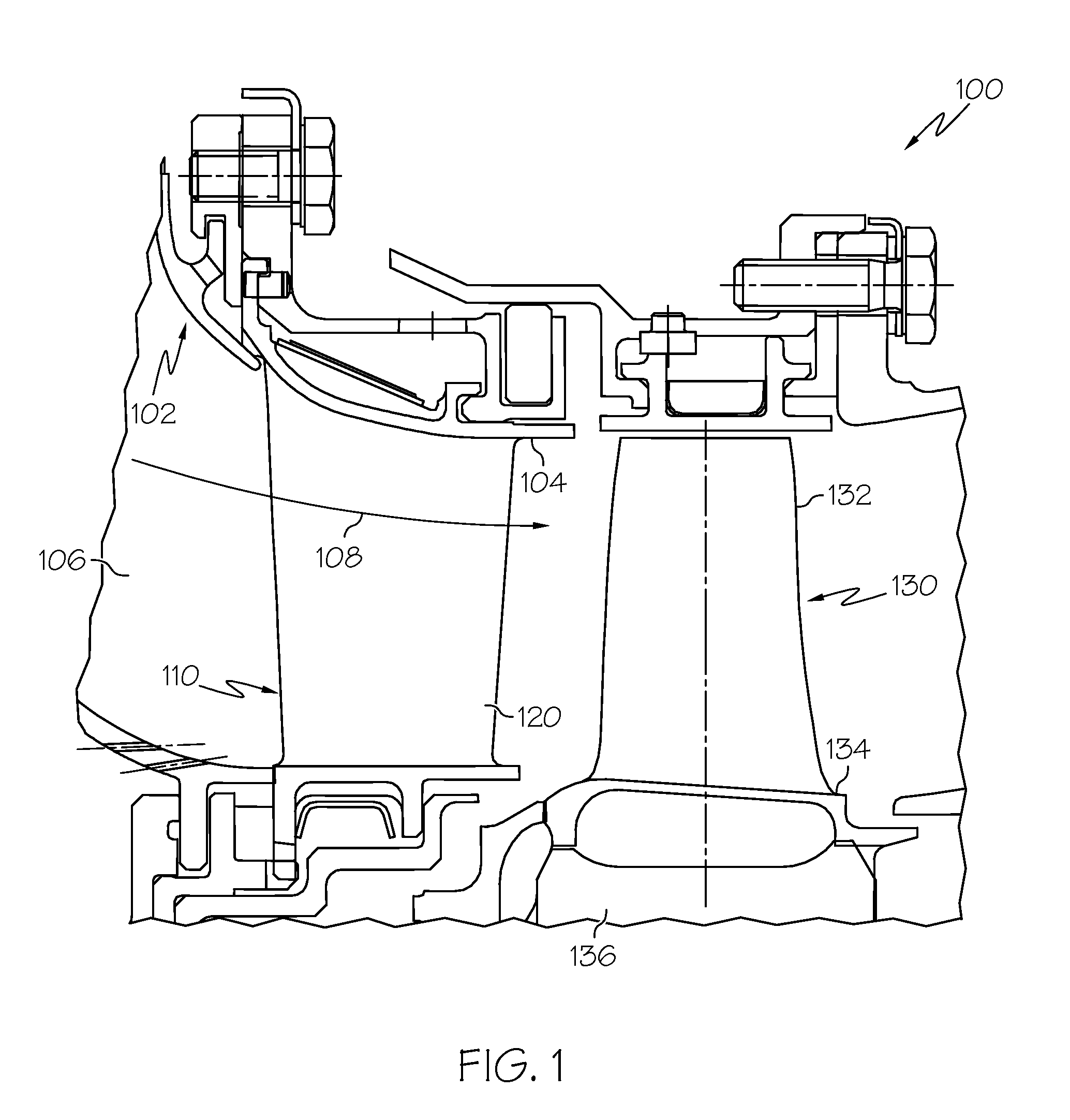
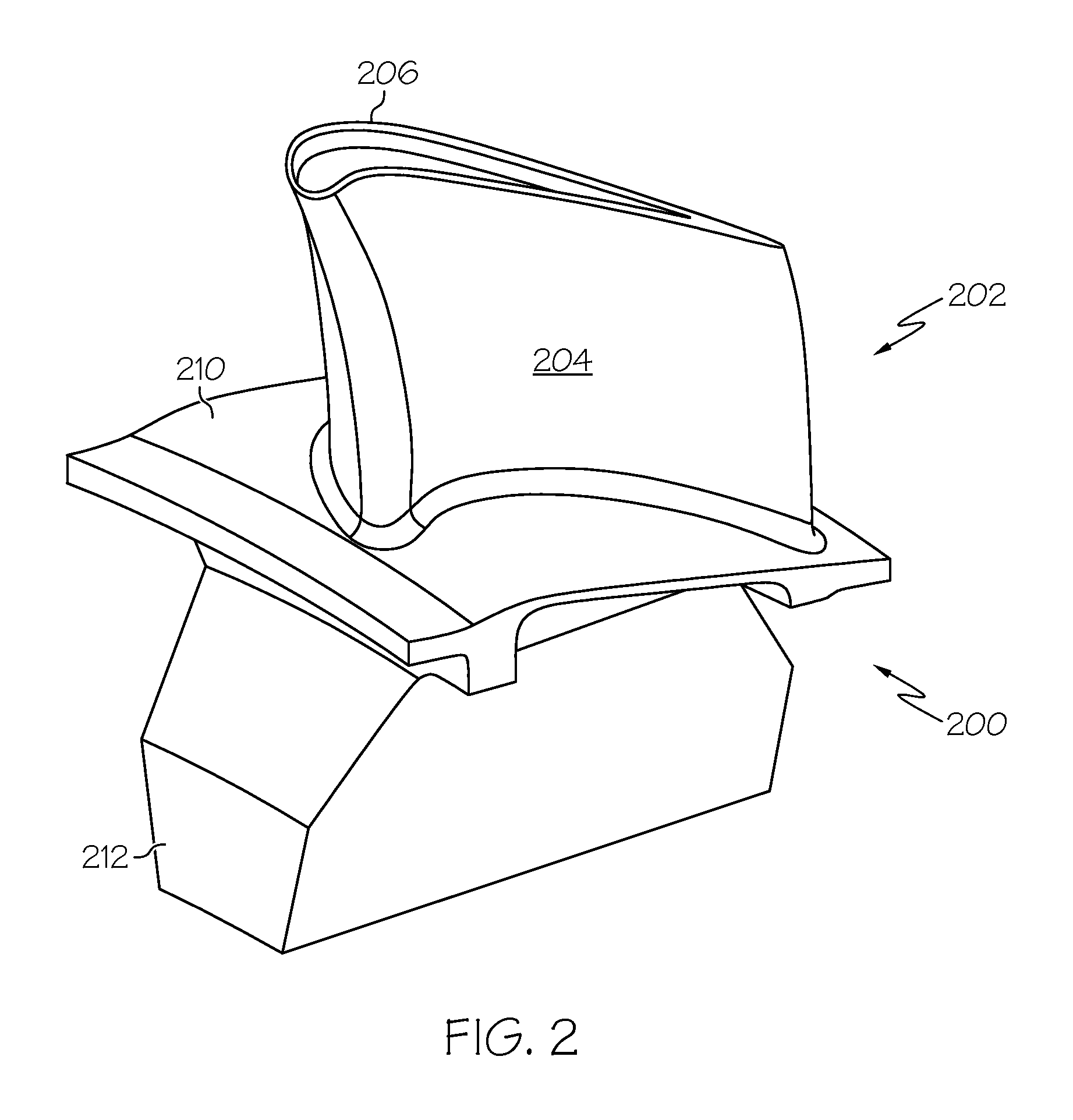
Broadly, exemplary embodiments discussed herein include methods for manufacturing turbine components of gas turbine engines. The turbine component is initially formed by an additive manufacturing technique such as direct metal laser sintering or electron beam melting. Other additive manufacturing methods may also be employed to create the component. The component is then encapsulated such that any surface connected defects (i.e. cracks, voids, lack of fusion and porosity) may effectively be considered internal defects. The encapsulated component then undergoes a consolidation treatment to substantially eliminate any defects, as well as any final treatments, to produce a finished turbine component....


PUM

PropertyMeasurementUnit
thicknessaaaaaaaaaa
pressureaaaaaaaaaa
temperatureaaaaaaaaaa

Abstract

A method is provided for manufacturing a turbine component. The method includes forming a first intermediate turbine article with an additive manufacturing process; encapsulating the first intermediate turbine article with an encapsulation layer to form a second intermediate turbine article; and consolidating the second intermediate turbine article to produce the turbine component.

Description

TECHNICAL FIELDThe present invention generally relates to turbine engines, and more particularly relates to methods for manufacturing turbine components for engines.BACKGROUNDGas turbine engines are generally known in the art and used in a wide range of applications, such as propulsion engines and auxiliary power unit engines for aircraft. In a typical configuration, a turbine section of the engine includes turbine components such as rows of stator airfoils and rotor blades disposed in an alternating sequence along the axial length of a generally annular hot gas flow path. The rotor blades are mounted on the periphery of rotor disks coupled to a main engine shaft. The stator airfoils are coupled to inner and outer endwalls and optimally direct hot combustion gases to the rotor blades, thus resulting in rotary driving of the rotor disks to provide an engine output.The stator airfoils and rotor blades typically have arcuate shapes with generally concave pressure sides and generally co...

Claims


Application Information

Patent Timeline
Patent Type & Authority Applications(United States)
IPC IPC(8): B22F3/26B23P17/00
CPCB22F3/1055B22F3/15B22F3/26B22F5/04Y10T29/49229F01D5/18Y02T50/673Y02T50/676F05D2230/22F01D5/147B33Y80/00Y02P10/25Y02T50/60B22F10/66B22F10/25B22F10/36B22F10/28B22F10/64
Inventor RYAN, DANIELMORRIS, MARK C.GODFREY, DONALD G.STARR, STEVE
Owner HONEYWELL INT INC
Why Eureka
Try Eureka