Connector

Active Publication Date: 2011-12-22
ORMON CORP
View PDF3 Cites 7 Cited by
  • Summary
  • Abstract
  • Description
  • Claims
  • Application Information

AI Technical Summary

Benefits of technology

[0020]According to this embodiment, the plane area of the entire elastic temporary holding portion becomes large and hence c

Problems solved by technology

However, because an inner side beam portion 83 of a nail 81 merely moves up and down in the connector described above, it is not easy to visually determine whether the FPC is correctly positioned or not when inserted into the connector.
In particular, further miniaturization is desired for the connector in recent years, and f

Method used


Image

  • Connector
  • Connector
  • Connector

Examples


Embodiment Construction

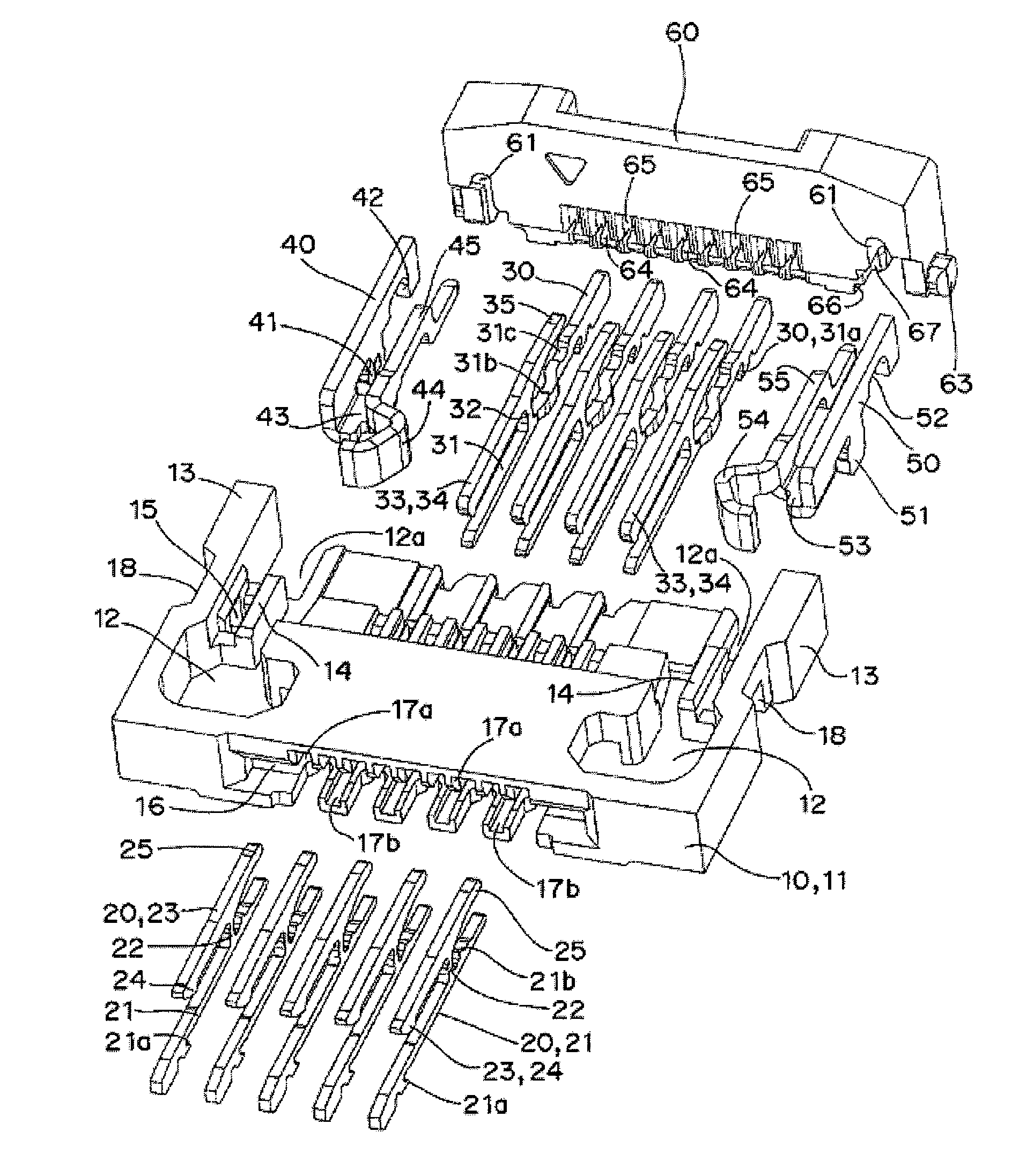
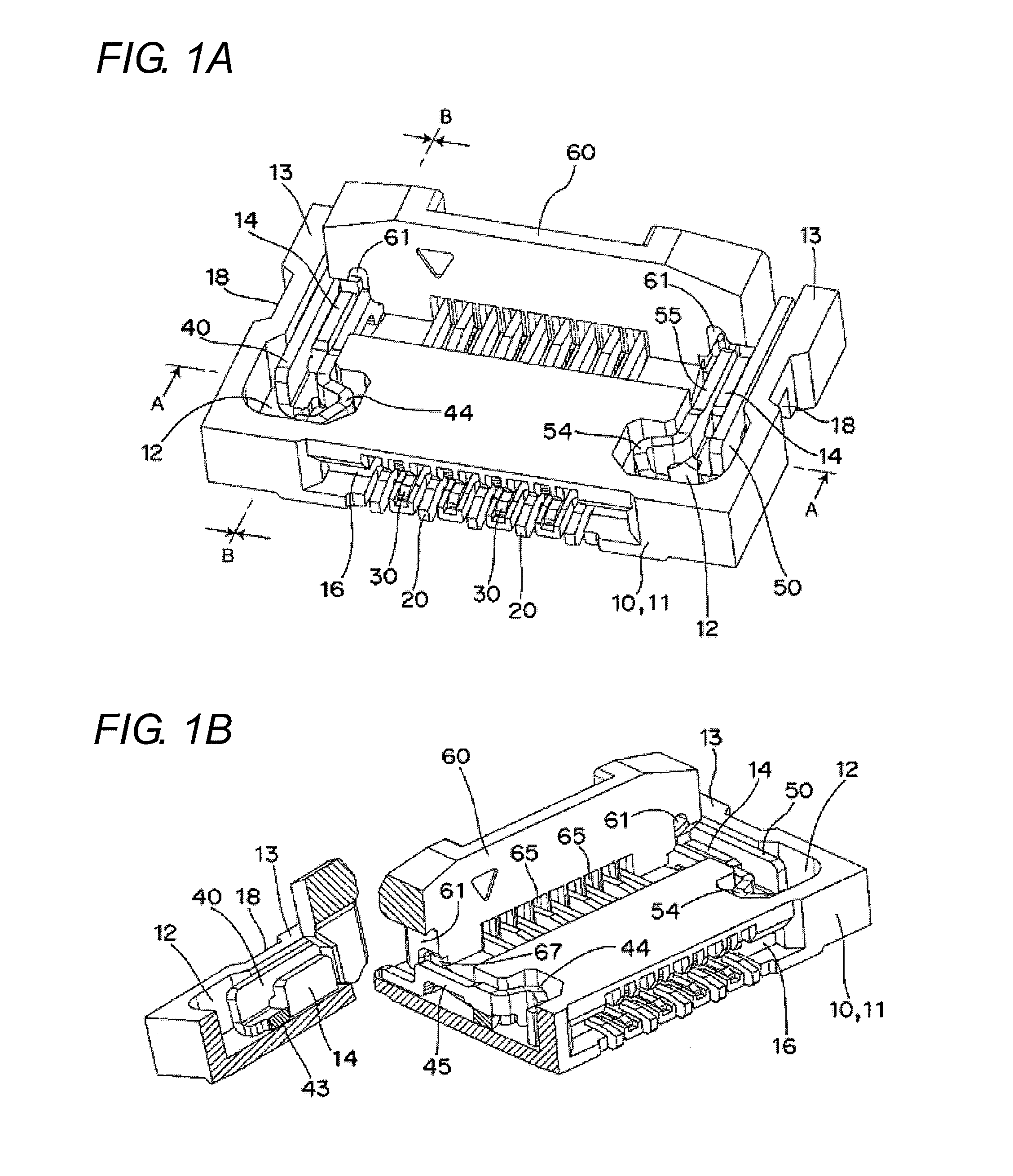
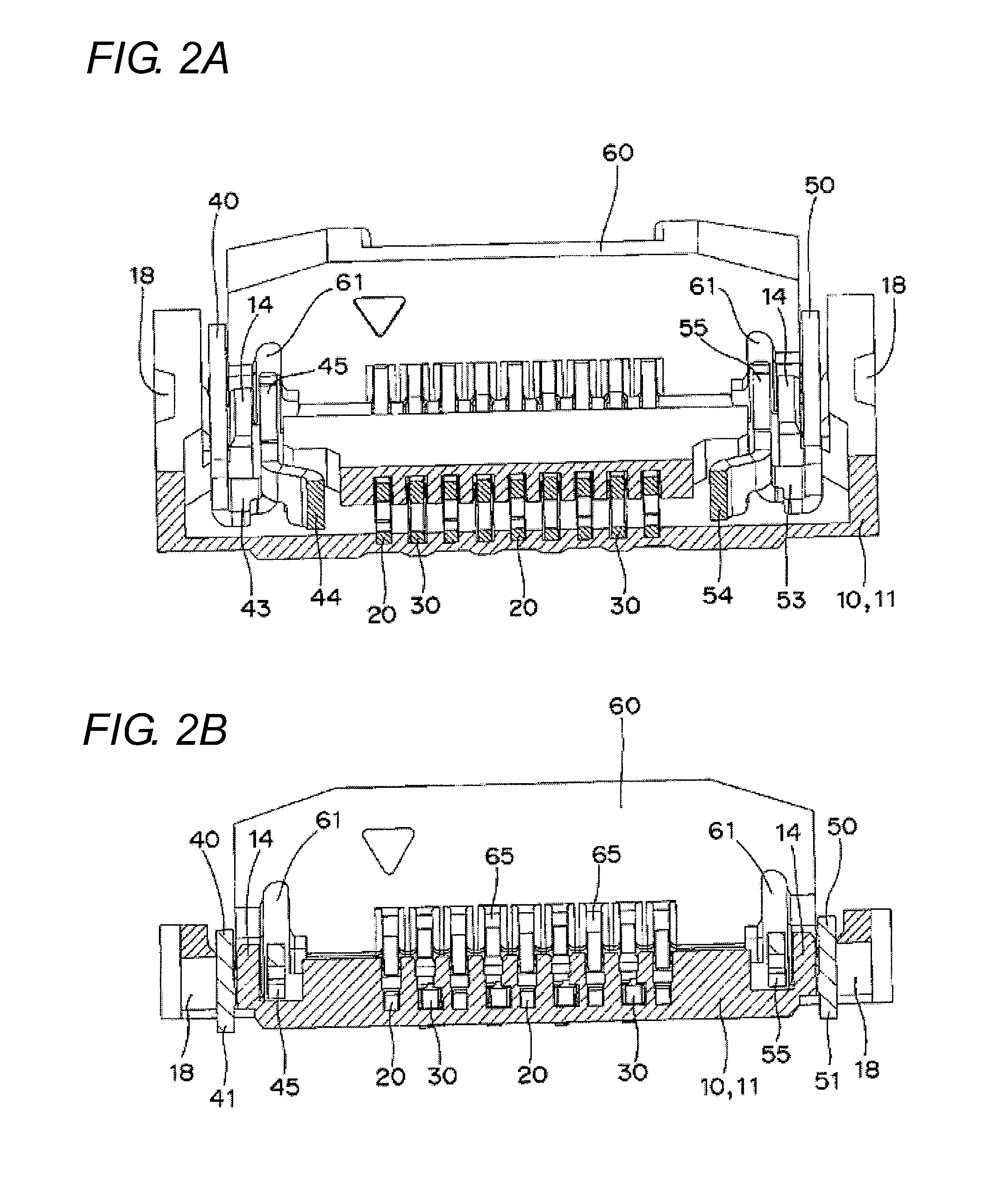
[0034]Embodiments of a connector according to the present invention will be described with reference to the accompanying drawings of FIGS. 1A to 13. In embodiments of the invention, numerous specific details are set forth in order to provide a more thorough understanding of the invention. However, it will be apparent to one of ordinary skill in the art that the invention may be practiced without these specific details. In other instances, well-known features have not been described in detail to avoid obscuring the invention. As shown in FIGS. 1A to 11B, a connector 10 according to a first embodiment is configured mainly by a base 11, first and second connection terminals 20, 30, a pair of support fittings 40, 50, and an operation lever 60.

[0035]The outer dimension of the connector 10 according to the first embodiment has a width dimension of 4.3 mm, a depth dimension of 3 mm, and a height dimension of 0.7 mm.

[0036]As shown in FIGS. 5A to 5C, the base 11 is formed with a side wall po...


PUM


Abstract

A connector has a base having an opening formed at a front surface of the base, to which a distal end of a flexible printed circuit is inserted, a plurality of insertion holes passing from the front surface to a rear surface arranged in a line at a predetermined pitch, and a fit-in recess at an upper surface of the base, a connection terminal press-fit into the insertion hole of the base from a side, a support fitting assembled to the fit-in recess of the base from an upper side, and including an elastic temporary holding portion capable of engaging a temporary holding cutout portion arranged on both side edges of the distal end of the flexible printed circuit, and an operation lever for supporting a turning shaft portion arranged at both side ends at a bearing of the support fitting in a turnable manner, and driving the connection terminal.

Description

BACKGROUND OF THE INVENTION[0001]1. Technical Field[0002]The present invention relates to connectors, and in particular, to an ultra-small connector for connecting a flexible printed circuit (hereinafter referred to as “FPC”).[0003]2. Related Art[0004]Conventionally, there is known a connector including a temporary holding mechanism for obtaining an inserting feeling and improving connection workability when inserting and connecting an FPC to the connector (see Japanese Unexamined Patent Publication No. 2008-277068). Thus, a predetermined inserting feeling can be obtained when the FPC is inserted into the connector, and the FPC can be temporarily held, as shown in FIG. 8, FIG. 9, and FIG. 12.[0005]However, because an inner side beam portion 83 of a nail 81 merely moves up and down in the connector described above, it is not easy to visually determine whether the FPC is correctly positioned or not when inserted into the connector.[0006]In particular, further miniaturization is desire...

Claims


Application Information

Patent Timeline
IPC IPC(8): H01R13/62
CPCH01R12/778H01R12/88H01R12/79H01R12/77H01R13/639
Inventor MATOBA, MASATOYOKOIGAWA, ATSUSHI
Owner ORMON CORP
Why Eureka
Try Eureka