Lighting control systems and methods

a control system and control system technology, applied in the direction of lighting devices, lighting sources, electrical devices, etc., can solve the problems of difficult retrofitting such buildings with a centrally controlled lighting system, high cost, and failure to turn off light sources in the desired manner

Inactive Publication Date: 2011-12-29
SYNAPSE WIRELESS
View PDF3 Cites 24 Cited by
  • Summary
  • Abstract
  • Description
  • Claims
  • Application Information

AI Technical Summary

Problems solved by technology

However, users often fail to turn off the light sources in the desired manner.
However, many existing buildings are equipped with manually-actuated switches and retrofitting such buildings with a centrally-controlled lighting system can be problematic and expensive.

Method used


Image

  • Lighting control systems and methods
  • Lighting control systems and methods
  • Lighting control systems and methods

Examples


Embodiment Construction

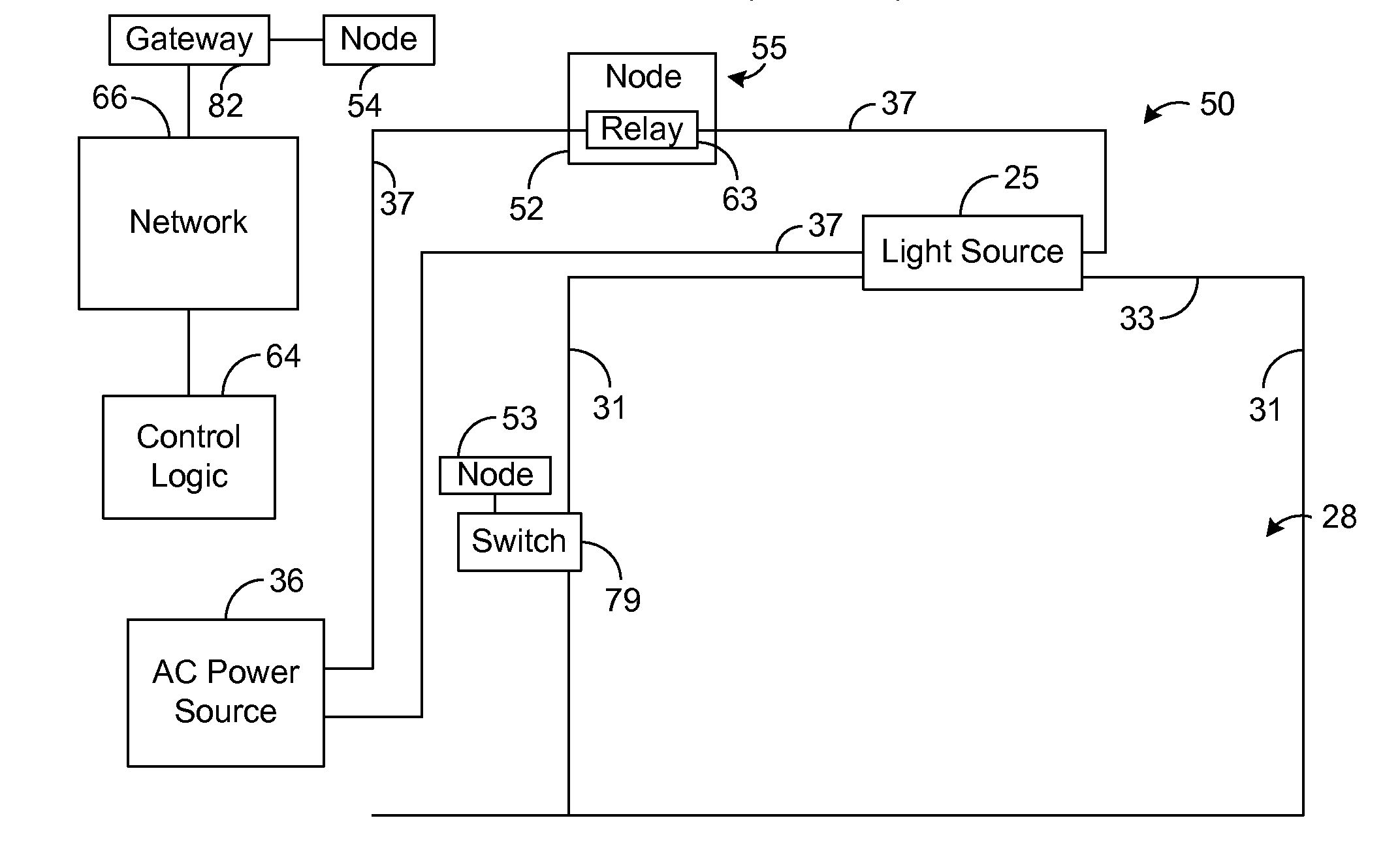
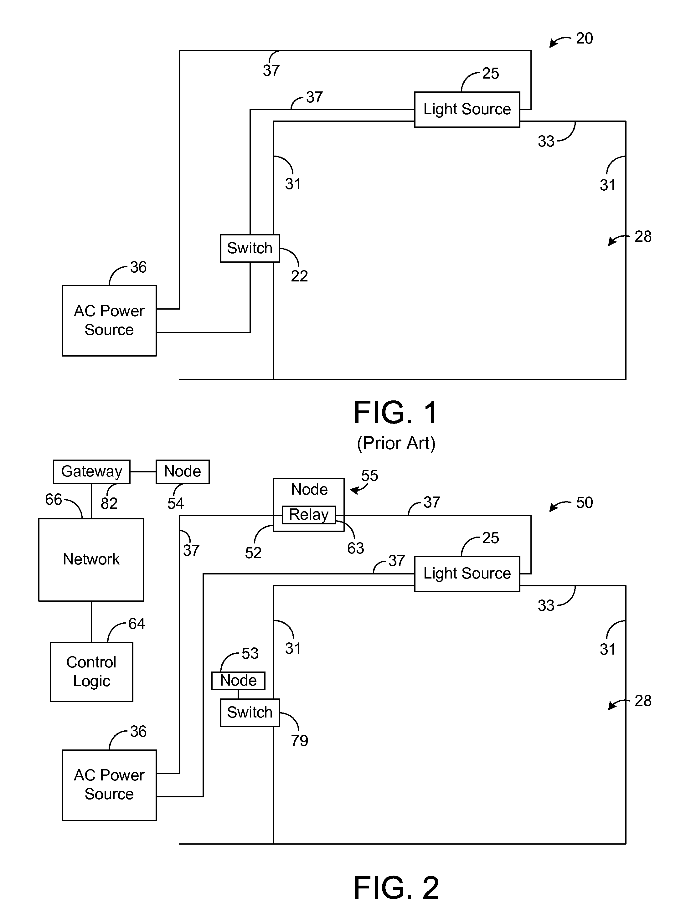
[0015]The present disclosure generally pertains to lighting control systems and methods. In one exemplary embodiment, a building having at least one light source controlled by a manually-actuated switch is retrofitted with a networked control system. In this regard, the manually-actuated switch is decoupled from a power line that provides power to the light source, and the power line is coupled to a node of a wireless network to provide in-line control of the light source. Another node of the network is coupled to a manually-actuated switch so that the node can receive inputs from such switch. Such node uses the wireless network to transmit data indicative of the inputs from the manually-actuated switch. Logic then uses such data to control the activation state of the light source via the in-line relay coupled to the power line.

[0016]Residential and commercial buildings often have wall-mounted switches for controlling lighting within such buildings. FIG. 1 depicts a typical lighting...


PUM


Abstract

The present disclosure generally pertains to lighting control systems and methods. In one exemplary embodiment, a building having at least one light source controlled by a manually-actuated switch is retrofitted with a networked control system. In this regard, the manually-actuated switch is decoupled from a power line that provides power to the light source, and the power line is coupled to a node of a wireless network to provide in-line control of the light source. Another node of the network is coupled to the manually-actuated switch so that the node can receive inputs from such switch. Such node uses the wireless network to transmit data indicative of the inputs from the manually-actuated switch. Logic then uses such data to control the activation state of the light source via the in-line relay coupled to the power line.

Description

CROSS REFERENCE TO RELATED APPLICATION[0001]This application claims priority to U.S. Provisional Patent Application No. 61 / 359,461, entitled “Lighting Control Systems and Methods” and filed on Jun. 29, 2010, which is incorporated herein by reference.RELATED ART[0002]Lighting systems within residential and commercial buildings have generally been controlled by manually-actuated switches, which are often mounted on building walls. To turn on a light source, a user manually moves a switch to one state and then moves the switch to another state to turn off the same light source. Oftentimes, it is desirable for one or more light sources to be turned off during certain times of the day and / or when there are no users present in order to conserve electrical power and reduce energy costs. However, users often fail to turn off the light sources in the desired manner. As an example, a user may neglect to turn off one or more light sources when leaving a room or turn on a light source in the mi...

Claims


Application Information

Patent Timeline
Patent Type & Authority Applications(United States)
IPC IPC(8): H05B37/02
CPCH05B37/0272H05B47/19
Inventor EWING, DAVID B.
Owner SYNAPSE WIRELESS
Why Eureka
Try Eureka