
Radiant electromagnetic energy management

a technology of radiant electromagnetic energy and management, applied in repeater circuits, line-transmission details, therapy, etc., can solve problems such as power levels, problems, and large power generation, and achieve the effect of discharging excess power

Inactive Publication Date: 2011-12-29
ROLLS ROYCE NORTH AMERICAN TECH
View PDF9 Cites 3 Cited by
  • Summary
  • Abstract
  • Description
  • Claims
  • Application Information

AI Technical Summary

Benefits of technology

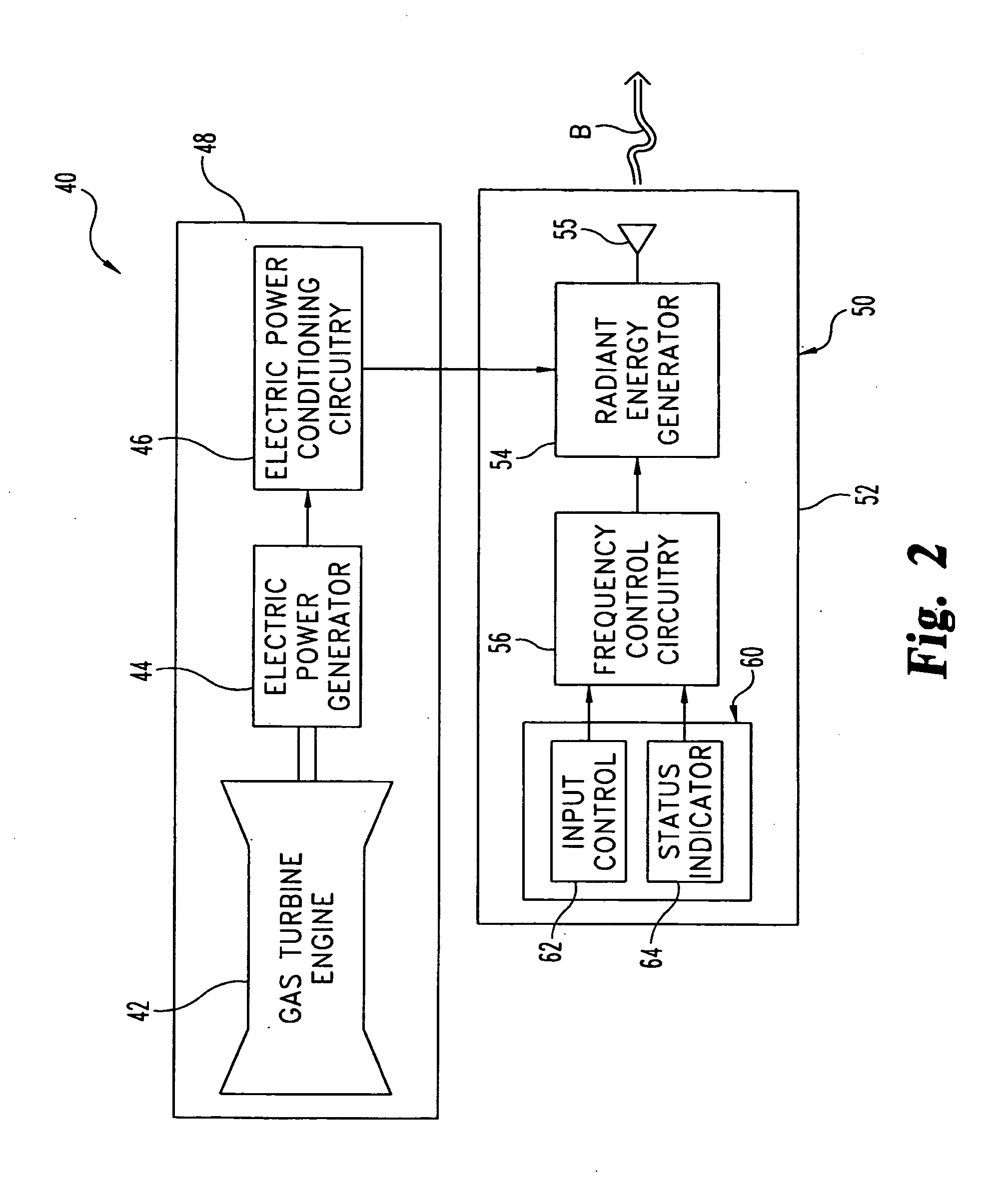
[0009]Yet another embodiment is a system including a gas turbine engine, an electric power generator, and a radiant energy device powered by electricity from the generator. This device includes an input control and frequency control circuitry responsive to this input control to generate a radiant electromagnetic energy output with the device in a selected one of two or more operating modes. The control circuitry provides for the generation of the electromagnetic energy output at a first frequency during one of these modes to dissipate excess power through atmospheric absorption of at least a portion of such output, and at a second frequency during another of these modes to disable a target brought in contact with the radiant electromagnetic energy output.

Problems solved by technology

Frequently, this kind of weapon requires the generation of a significant amount of power to effectively impede an enemy; however, when the weapon is not being applied to a target, such power levels are typically not needed—and may even become problematic.
Unfortunately, powering down between target applications often decreases the speed with which the weapon can be applied later, and may be unacceptably inefficient for a given type of power source.
Unfortunately, these approaches tend to add an undesirable amount of weight.

Method used


Image

  • Radiant electromagnetic energy management
  • Radiant electromagnetic energy management
  • Radiant electromagnetic energy management

Examples


Embodiment Construction

[0018]While the present invention may be embodied in many different forms, for the purpose of promoting an understanding of the principles of the invention, reference will now be made to the embodiments illustrated in the drawings and specific language will be used to describe the same. It will nevertheless be understood that no limitation of the scope of the invention is thereby intended. Any alterations and further modifications in the described embodiments, and any further applications of the principles of the invention as described herein are contemplated as would normally occur to one skilled in the art to which the invention relates.

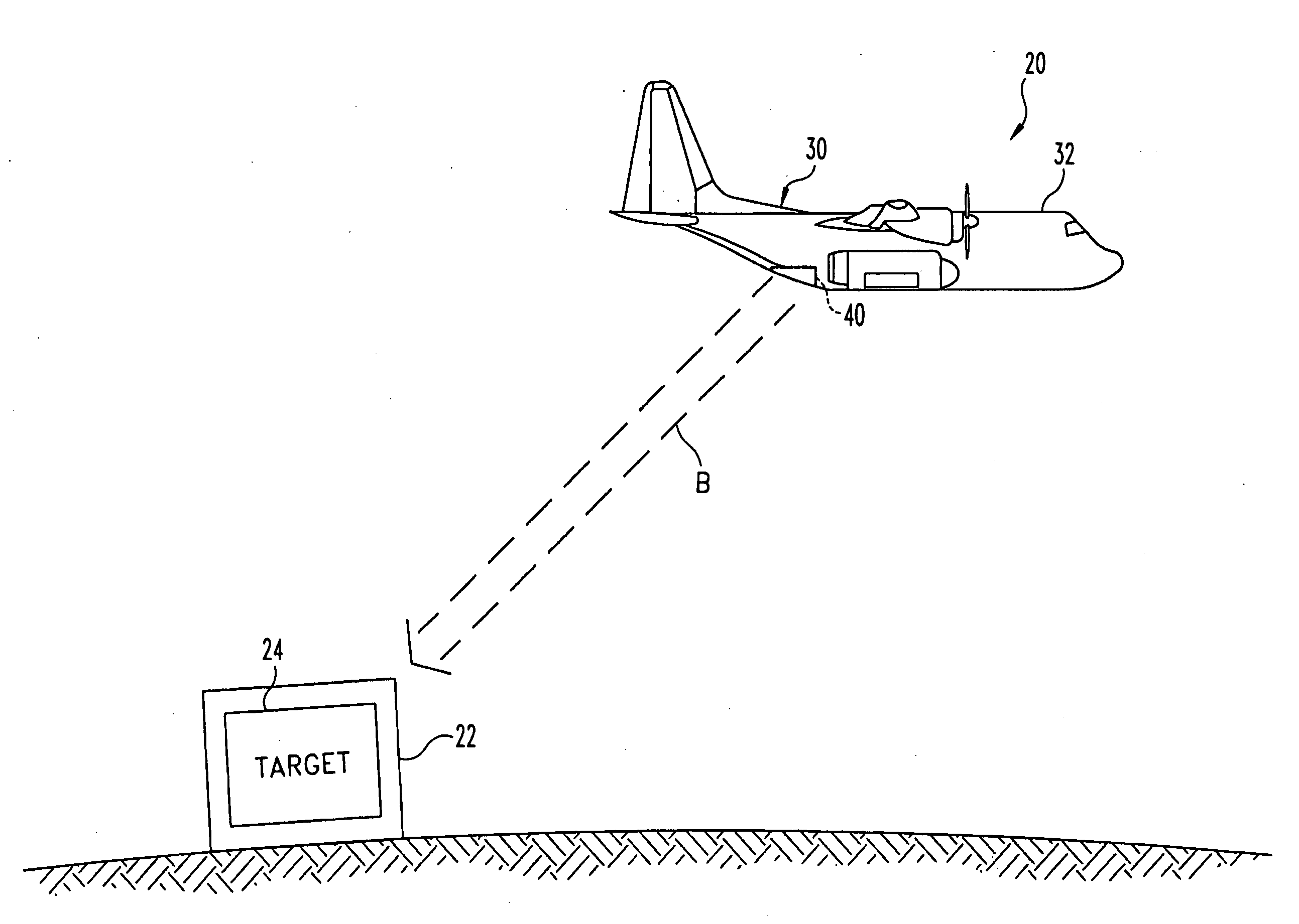
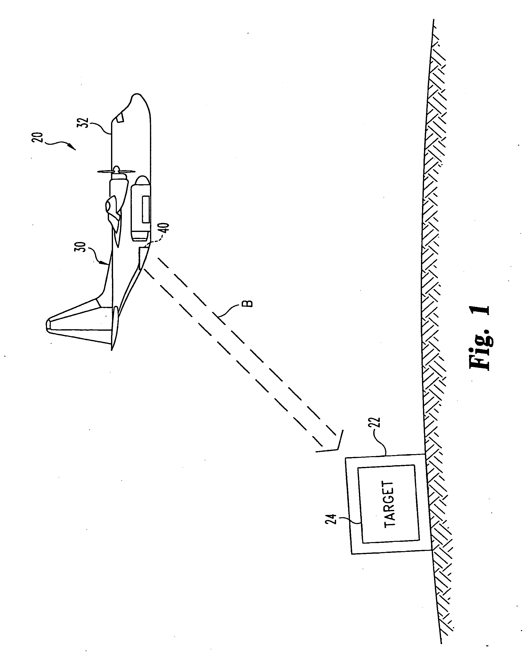
[0019]FIG. 1 illustrates a radiant energy directing system 20 in an airborne application. System 20 includes an aircraft 30 directing a radiant electromagnetic energy beam B towards a targeted building 22. Beam B is generated with a radiant energy weapon 40 that is carried by aircraft 30. Building 22 encloses a weapon target 24. Beam B is ultimatel...


PUM


Abstract

A device provides a radiant electromagnetic energy output. During standby operation of the device, the output is provided at one or more frequencies selected to dissipate excess power through atmospheric absorption. Circuitry is included to tune the output of the device to a second frequency different than the first frequency for various directed energy applications that make use of the excess power. The circuitry can be arranged to further utilize frequency agility for power dissipation, to provide different operating modes involving a radiant output, or the like.

Description

CROSS-REFERENCE TO RELATED APPLICATION[0001]The present application is a continuation of U.S. Utility patent application Ser. No. 11 / 219,931 filed 6 Sep. 2005, which is incorporated herein by reference in its entirety.BACKGROUND[0002]The present application relates to the management of radiant electromagnetic energy, and more particularly, but not exclusively, relates to a frequency adjustable directed electromagnetic energy system.[0003]Various High-Power Microwave (HPM) devices and other apparatus have been developed to provide directed energy weaponry. Frequently, this kind of weapon requires the generation of a significant amount of power to effectively impede an enemy; however, when the weapon is not being applied to a target, such power levels are typically not needed—and may even become problematic. Unfortunately, powering down between target applications often decreases the speed with which the weapon can be applied later, and may be unacceptably inefficient for a given type...

Claims


Application Information

Patent Timeline
Patent Type & Authority Applications(United States)
IPC IPC(8): H04B3/36B01J19/12
CPCF41H13/00
Inventor DUGE, ROBERT T.
Owner ROLLS ROYCE NORTH AMERICAN TECH
Learn More