Use of individual blade control on a propeller or rotor in axial flight for the purpose of aerodynamic braking and power response modulation

a technology of aerodynamic braking and power response modulation, applied in the field of rotorcraft, can solve the problems of large deviation from linear relationships, excess airfoil drag, rotational acceleration that increases shaft rpm, etc., and achieves the effects of improving aerodynamic braking, improving aircraft flight dynamics, and reducing torque stress

Active Publication Date: 2018-12-06
KAREM AIRCRAFT INC
View PDF0 Cites 16 Cited by
  • Summary
  • Abstract
  • Description
  • Claims
  • Application Information

AI Technical Summary

Benefits of technology

[0016]The inventive subject matter contemplates systems, devices, and methods to improve aircraft flight dynamics, for example improving aerodynamic braking with reduced (or zero) torque stress on the drive shaft, as well as increasing flight maneuverability independent of rapid engine response by rapidly modulating required driveshaft torque.
[0018]One approach to rapidly modulating required driveshaft torque involves operating the engine at a higher than required power, while dissipating the excess power in a way that can be modulated quickly. Thus, rapid variations in the amount of dissipated power offer enhanced maneuverability and responsiveness. Rotorcraft operators normally seek to maximize the lifting efficiency of rotor systems because additional efficiency reduces the power required to lift a load and reduces fuel consumption. But a rotor capable of rapidly modulating its lifting efficiency further provides enhanced maneuverability and fuel efficiency.

Problems solved by technology

At both very high airfoil angles of attack and very low airfoil angles of attack, aerodynamic separation causes large deviation from the linear relationships by both reducing the airfoil lift curve slope and by creating excess airfoil drag.
This energy absorption produces shaft torque input, and results in rotational acceleration that increases shaft RPM, unless friction or some other mechanism acts to dissipate the absorbed energy.
In many applications (such as turboprop aircraft) the primary dissipative mechanism is friction in the drive system, which increases as a function of increasing shaft speed, thus the practical amount of air braking effect achievable is limited by the maximum RPM for which the propeller or rotor is rated.
Thus, one issue is that conventional propeller aerodynamic braking dissipates energy absorbed from the airstream using friction in the drive train, and is limited by the thermal and mechanical limits of the drive system.
Despite their many advantages, turboshaft engines have the disadvantage that they respond slowly to changes in power command, frequently with well over a one-second response delay depending on operating condition.
This slow power response is one factor limiting the aggressiveness with which many rotorcraft can maneuver.
As such, another issue is that during operating periods where enhanced maneuverability is required of a rotorcraft, generally requiring greater torque from the drive shaft, increases in power delivered by an engine can be slow relative to desired changes in power delivered through the blades.

Method used


Image

  • Use of individual blade control on a propeller or rotor in axial flight for the purpose of aerodynamic braking and power response modulation
  • Use of individual blade control on a propeller or rotor in axial flight for the purpose of aerodynamic braking and power response modulation
  • Use of individual blade control on a propeller or rotor in axial flight for the purpose of aerodynamic braking and power response modulation

Examples


Embodiment Construction

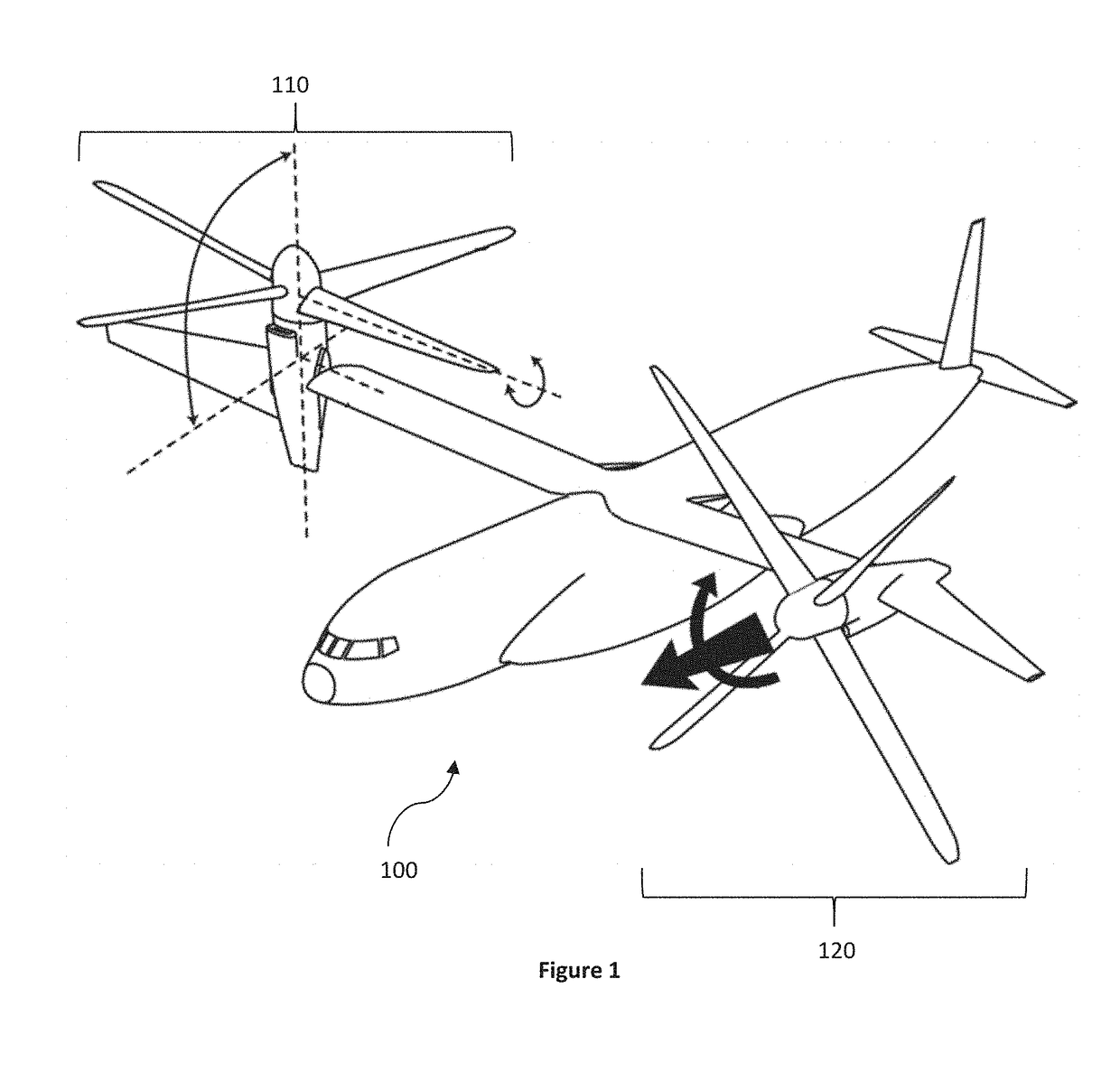
[0048]The inventive subject matter contemplates systems, devices, methods, and uses of IBC-capable propellers or rotors to modify flight characteristics or dynamics of aircraft, for example (1) to achieve greater aerodynamic braking effectiveness than would otherwise be possible with non-IBC propellers or rotors, or (2) to rapidly modulate the amount of driveshaft torque required to drive a rotor or propeller while maintaining constant thrust (thus varying the effective lifting efficiency of the rotor).

[0049]Various objects, features, aspects and advantages of the inventive subject matter will become more apparent from the detailed description of preferred embodiments herein, along with the accompanying drawing figures in which like numerals represent like components.

[0050]Aerodynamic Braking

[0051]The inventive subject matter provides apparatus, systems and methods in which IBC-capable propellers or rotors are used to achieve greater braking effectiveness than would otherwise be pos...


PUM


Abstract

Systems and methods are contemplated for favorably improving flight dynamics of aircraft, including enhanced aerodynamic braking and improved flight maneuverability. Air braking systems selectively position a first set of blades at a negative thrust pitch to product a net negative thrust across first and second sets of blades, while balancing torque of the drive shafts to zero. First and second sets of IBC blades can be driven by the same shaft or torque-linked shafts. Flight maneuver systems operate a powerplant at a high power mode, and dissipate the energy from the high power output by positioning a first set of IBC blades at a low efficiency pitch while maintaining constant thrust. As increased or rapid flight maneuverability is required, the first set of blades is positioned toward a high efficiency pitch to instantly increase thrust to the aircraft without requiring a related increase in energy output from the powerplant.

Description

PRIORITY[0001]This application claims priority to U.S. Provisional Application Ser. No. 62 / 513,925 (filed Jun. 1, 2017) and U.S. Provisional Application Ser. No. 62 / 513,930 (filed Jun. 1, 2017), the disclosures of which are each incorporated herein by reference.FIELD OF THE INVENTION[0002]The field of the invention is rotorcraft.BACKGROUND[0003]Propellers and rotors comprise lifting surfaces azimuthally distributed around the axis of a rotating shaft. They are generally utilized to provide propulsive forces for controlling the motion of an aircraft. Propellers may have one or more blades, and examples with two, three, four, five, six, and seven blades are common.[0004]Some propellers utilize blades where blade pitch (lifting surface angle of incidence relative to the tangential direction due to shaft rotation) is mechanically fixed (fixed-pitch propellers). Other propellers, and some rotors, incorporate pitch-control mechanisms, enabling blade pitch for all blades to simultaneously ...

Claims


Application Information

Patent Timeline
Patent Type & Authority Applications(United States)
IPC IPC(8): B64C27/80B64C29/00B64D27/24B64D27/10B64C27/72
CPCB64C27/80B64C29/0033B64D27/24B64D27/10B64C27/72B64C2027/7205Y02T50/30
Inventor KAREM, ABETIGNER, BENJAMIN
Owner KAREM AIRCRAFT INC
Why Eureka
Try Eureka