Device for powering electric or electronic devices operatively associated with a circuit breaker

a technology of electric or electronic devices and circuit breakers, which is applied in the direction of electric variable regulation, process and machine control, instruments, etc., can solve the problems of insufficient accuracy of said regulation, inability to guarantee stable power supply conditions for an indefinite period, and limited voltage, so as to achieve high energy efficiency and dissipate any excess power

Active Publication Date: 2010-03-30
ABB SPA
View PDF5 Cites 1 Cited by
  • Summary
  • Abstract
  • Description
  • Claims
  • Application Information

AI Technical Summary

Benefits of technology

[0021]The main technical aim of the present invention is to realize a power supply device for one or more electric or electronic device(s) operatively associated with a low-voltage circuit breaker that enables the previously-described drawbacks to be overcome, and particularly that functions properly for a very wide range of network parameters (VPH or IL) and absorption parameters (PS) of the device(s) being powered. In the context of this technical aim, one object of the present invention is to realize a device for powering one or more electric or electronic device(s) operatively associated with a low-voltage circuit breaker that has a high energy efficiency and drastically reduces the situations in which it is necessary to passively dissipate any excess power.
[0022]Another object of the present invention is to realize a power supply device for one or more electric or electronic device(s) operatively associated with a low-voltage circuit breaker that enables a reduction in overheating phenomena, thereby reducing the exposure of the components to a rapid consequent deterioration. Another object of the present invention is to realize a power supply device for one or more electric or electronic device(s) operatively associated with a low-voltage circuit breaker that does not generate significant disturbances of electromagnetic type. Yet another object of the present invention is to realize a power supply device for one or more electric or electronic device(s) operatively associated with a low-voltage circuit breaker that has limited overall dimensions and is reliable and easy to manufacture at relatively low costs.

Problems solved by technology

The use of a network of passive and / or discrete elements makes it difficult to guarantee stable power supply conditions for an indefinite period of time, especially in the event of variations in the power supply PS demanded by the auxiliary loads and / or a variability of the phase voltage VPH.
It has been demonstrated, however, that the tolerances and physical limits of the components used and consequent phenomena of inertia, hysteresis, transition and thermal drift mean that the alternate switching between “on” and “off” states does not take place at exactly the right time: it is not instantaneous, but occurs in far from negligible fractions of the period TSW.
As a result, the voltage can only be partially limited on the basis of the instantaneous correction of the duty cycle at a given switching frequency fSW, and said regulation cannot be sufficiently accurate.
The large number of passive and discrete components required may also become a critical issue in terms of overall dimensions and costs, however.
The use of power supply devices based on this type of approach is consequently scarcely flexible in relation to the network voltage, entailing a consequent increase in production, installation and operating costs.
Moreover, the high energy consumption statistically observable due to dissipation induces a considerable heating and greater deterioration of the components, as well as having a far more negative fallout on the energy balance of the main network than would be due to the power supply actually delivered for the auxiliary loads.
This poor energy efficiency can give rise to temperatures as high as 140° C. in some of the components involved.
Another drawback of the power supply devices of the previously-described type concerns the so-called startup time TSU, i.e. the time it takes to reach a steady state: being relatively long, this can become a critical issue when it comes to powering a protection device, for instance.
Problems can occur, for example, when the circuit breaker is closed in latent short-circuit conditions: in such cases, any delay in the power supply to the protection device tends to be translated into damage to the system and to the circuit breaker.
The power conducted from the network consequently cannot be transferred directly to the auxiliary loads in this case either.
A further drawback of the power supply devices of the above-described type lies, here again, in the lengthy startup time TSU.
In fact, since the initial value of the line currents IL is generally not known, it is impossible to have any real guarantee; at best, the minimum time always ranges from 16 ms to 20 ms and, for the reasons previously explained, that can hardly be considered satisfactory, especially for the purpose of protection devices.
Another limit intrinsic in the use of current transformer sensors lies in that they can only work in networks powered in AC, not in applications in DC.
Another drawback common to both types of solution described above derives from the fact that the optimal switching frequency fSW of the shifters is around a few thousand Hertz, and therefore considerably higher than the mains frequency (which is normally 50 or 60 Hz), and this circumstance is translated into a considerable risk of electromagnetic disturbance relating, for instance, to the signals controlled by a protection device, but also in the form of unwanted backflows into the main electric network.
Another disadvantage common to the two known solutions previously described lies in their low general performance or energy efficiency (which becomes even worse when the dissipators take effect); the energy consumption of the power supplies described may even be sufficient to cause a considerable disruption in the energy balance of the stretch of power network where the circuit breaker is installed with its related devices to power.

Method used


Image

  • Device for powering electric or electronic devices operatively associated with a circuit breaker
  • Device for powering electric or electronic devices operatively associated with a circuit breaker
  • Device for powering electric or electronic devices operatively associated with a circuit breaker

Examples


Embodiment Construction

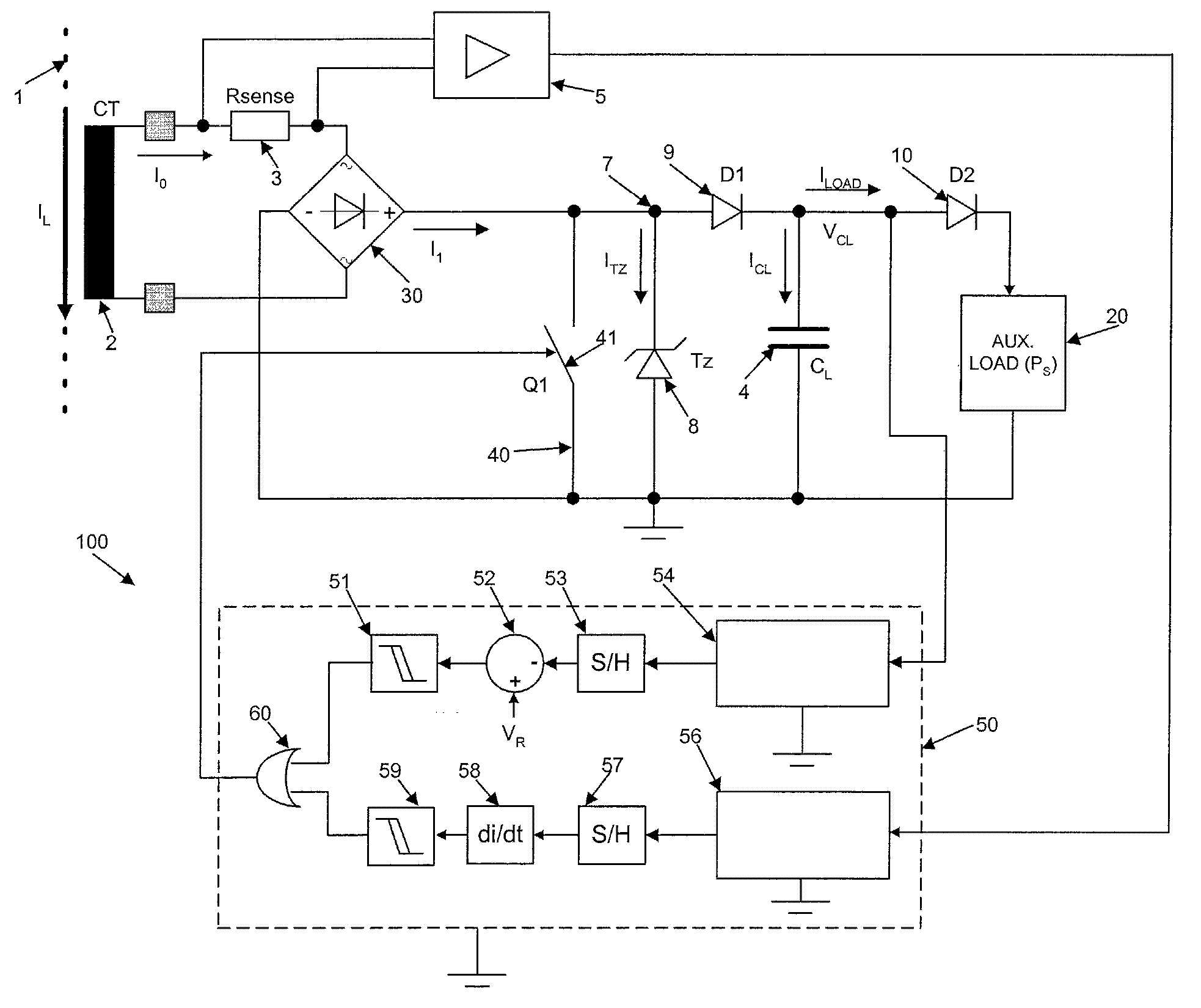
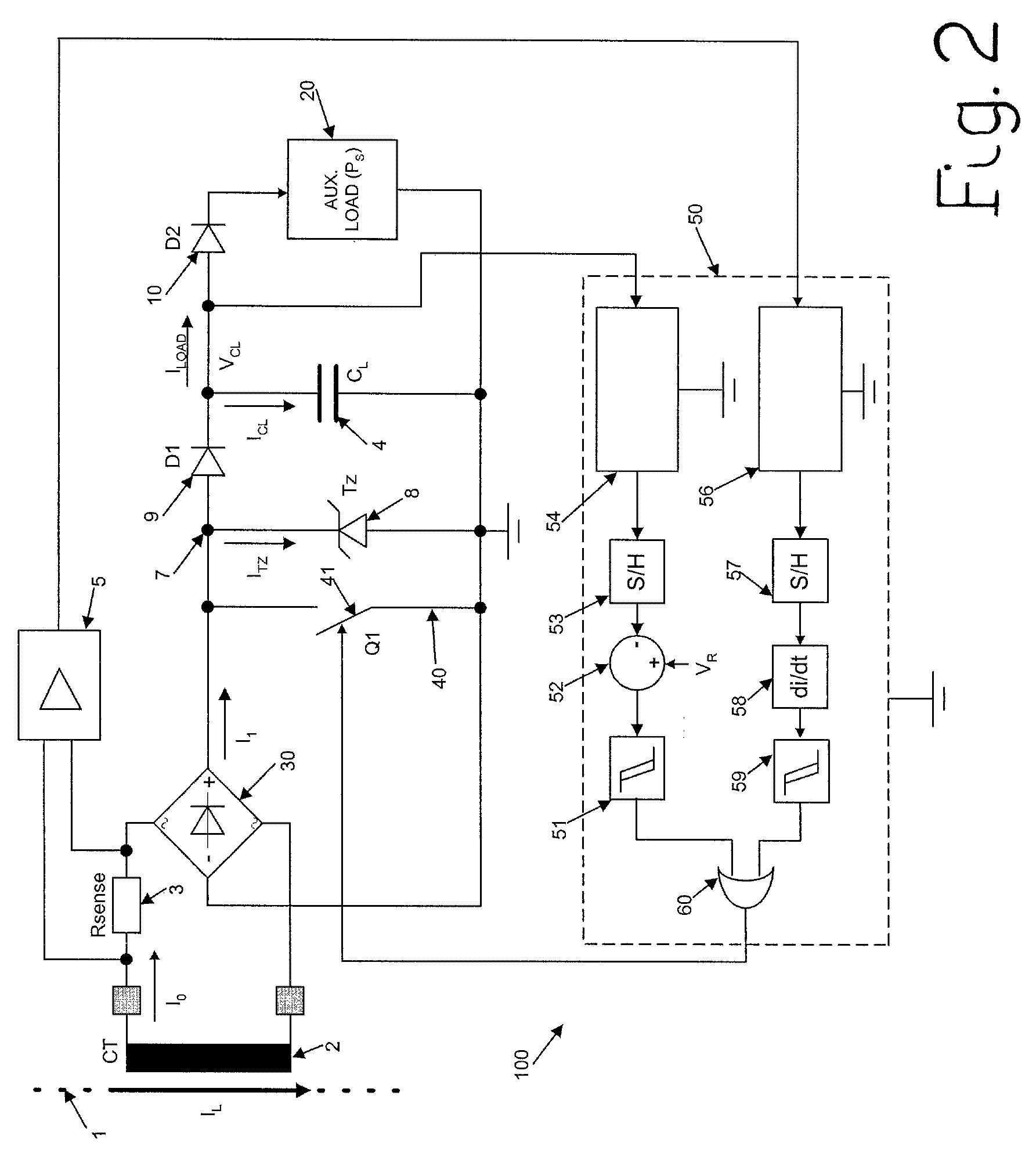
[0036]FIG. 2 schematically illustrates a first embodiment of the power supply device according to the invention, indicated globally by the reference numeral 100, which comprises: means suitable for taking power from a power supply line 1; electronic regulating means that receive the power collected by the means for taking power 1, preferably in the form of a current, as input and that deliver a supply voltage (Vout) with a value coming within a range established in relation to a preset reference voltage (VR) to the electric / electronic device(s) being powered, schematically indicated by the reference numeral 20.

[0037]To facilitate the description, only a single device 20 to power is illustrated in the figures, although several electric / electronic devices 20 may clearly be powered simultaneously by the device according to the invention.

[0038]Moreover, the figures only illustrate a single conductor 1 from the power supply line; this is on the understanding that the content of the follo...


PUM


Abstract

A device for powering one or more electric / electronic devices operatively associated with a low-voltage circuit breaker takes energy from a power supply line. An electronic regulator receives the energy collected as an input and delivering as an output to the electric / electronic device a power supply voltage (Vout) having a value within a preset range with respect to a reference voltage (VR). The electronic regulator includes an energy storage device chargeable by the energy collected, at the terminals of which a voltage (VCL) is established that is indicative of the power supply voltage (Vout) delivered to the electric / electronic device. A circuit enables / disables the charging of the storage device, and a feedback circuit receives a signal indicative of the voltage (VCL) at the terminals of the storage device and sends a signal to the enabling / disabling circuit to trigger the disabling or enabling of the charging process in order to keep the value of the voltage at the terminals of the storage device within a preset range. The feedback circuit enables the charging phases so as to power the storage device continuously up until the value of the voltage at their terminals comes within the preset range.

Description

FIELD OF THE INVENTION[0001]The present invention relates to a device for powering one or more electric / electronic device(s) operatively associated with a low-voltage circuit breaker, i.e. for working voltages up to 1 kV. More in particular, the present invention relates to a high-performance power supply device for applications in both alternating current (AC) and direct current (DC).BACKGROUND OF THE INVENTION[0002]According to the known state of the art, there are low-voltage circuit breakers of various types, depending on the number of poles (i.e. single- or multiple-pole), or depending on the type of operation (e.g. power line circuit breakers, residual current circuit breakers for detecting fault currents to earth, disconnector circuit breakers, and so on). These circuit breakers are generally characterized in that they are associated with electric or electronic devices, such as protection devices that automatically open the circuit breaker in the event of certain conditions (...

Claims


Application Information

Patent Timeline
Patent Type & Authority Patents(United States)
IPC IPC(8): H02J7/00
CPCH02H1/066H02H1/06H02H1/063
Inventor GABELLO, ANTONIO MARIAGRITTI, PAOLO
Owner ABB SPA
Why Eureka
Try Eureka