Camera layout determination support device

a technology of layout determination and support device, which is applied in the direction of television system, program control, instruments, etc., to achieve the effect of accurate delivery of customer needs and efficient cover of the area

Inactive Publication Date: 2011-12-29
HITACHI INFORMATION & CONTROL SOLUTIONS LTD
View PDF4 Cites 55 Cited by
  • Summary
  • Abstract
  • Description
  • Claims
  • Application Information

AI Technical Summary

Benefits of technology

[0056]However, with respect to the method that a sales people hears a customer need and consults with an expert and the expert determines the camera layout and camera setting, there is such a problem that, for example, an accurate delivery of the customer need to the expert is difficult, an accuracy of the camera layout depends on technique of the expert, and effects priority camera which photographs, for example, a face is arranged in advance and cameras having a wider visual field are arranged in the remaining space, then, the cameras can be arranged so as to efficiently cover the area.

Problems solved by technology

However, with respect to the method that a sales people hears a customer need and consults with an expert and the expert determines the camera layout and camera setting, there is such a problem that, for example, an accurate delivery of the customer need to the expert is difficult, an accuracy of the camera layout depends on technique of the expert, and effects priority camera which photographs, for example, a face is arranged in advance and cameras having a wider visual field are arranged in the remaining space, then, the cameras can be arranged so as to efficiently cover the area.

Method used


Image

  • Camera layout determination support device
  • Camera layout determination support device
  • Camera layout determination support device

Examples


embodiment 1

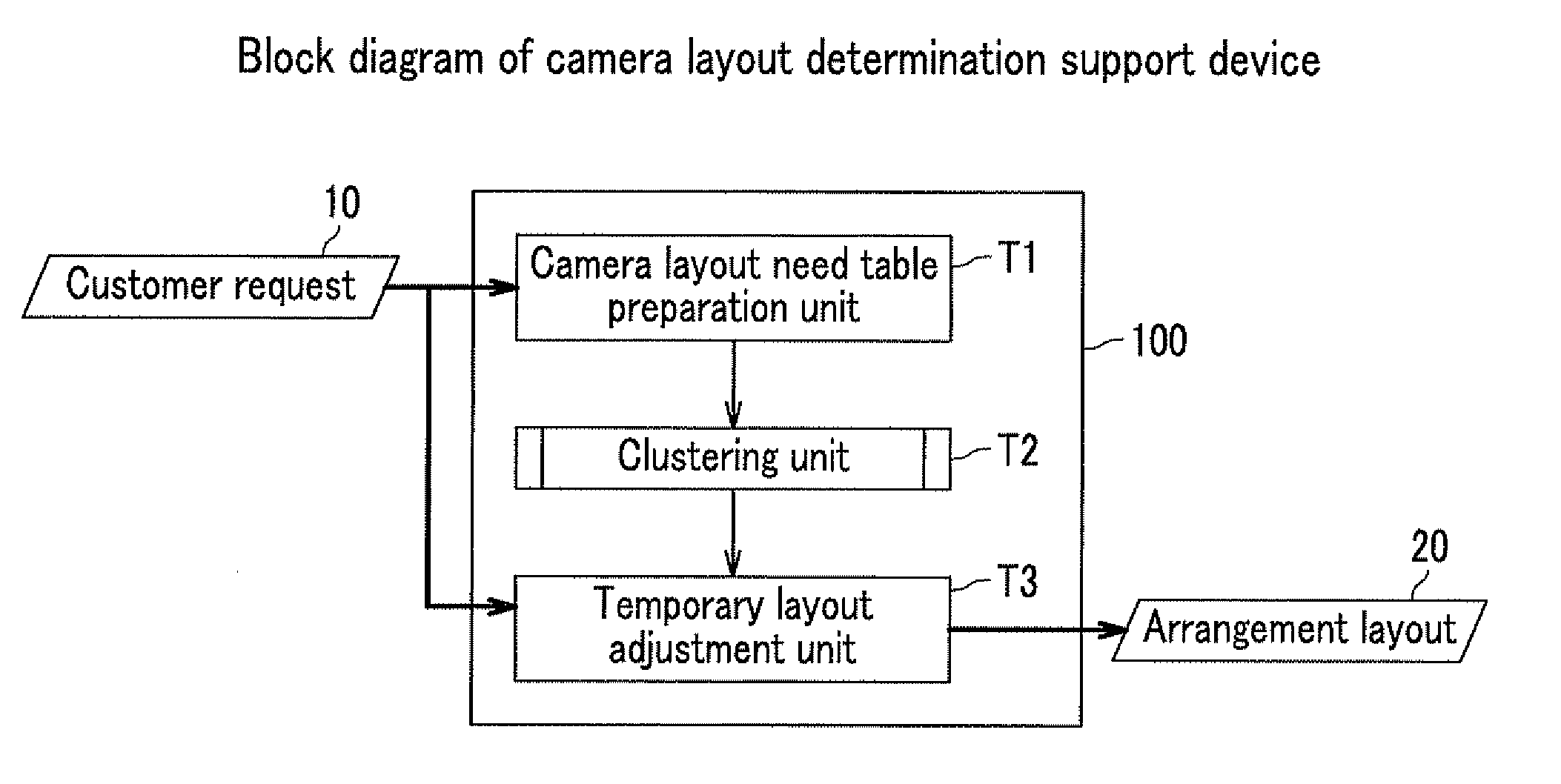
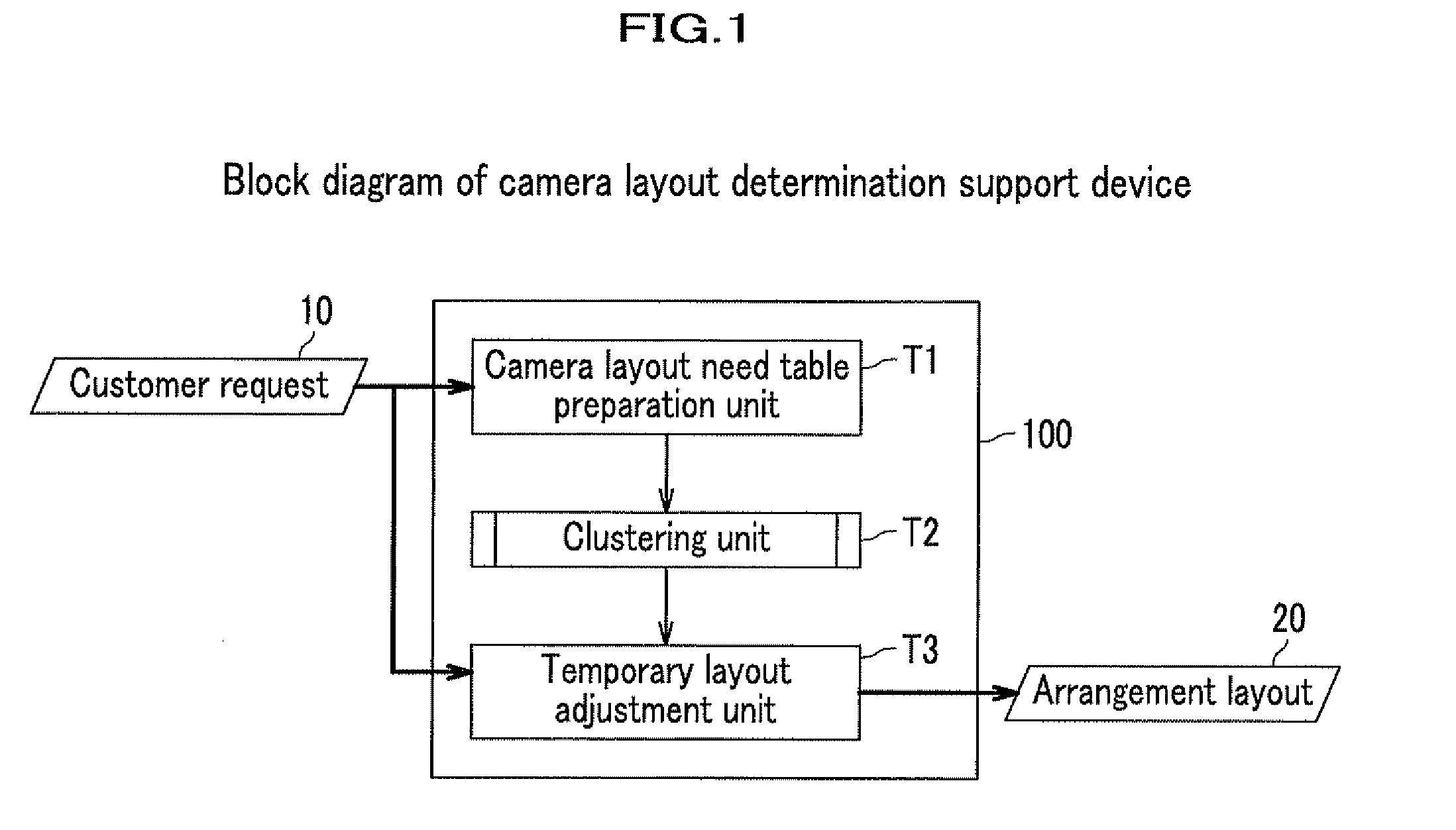
[0027]FIG. 1 is a block diagram showing one example of a camera layout determination support device 100 according to EMBODIMENT 1 of the present invention. The camera layout determination support device 100 inputs a customer request 10 and outputs an arrangement layout 20 of surveillance cameras that satisfies the customer request 10. Here, the customer request 10 includes, for example, a surveillance layout showing a layout of surveillance area, a desired function required for a camera in a given area in the surveillance layout (hereinafter, referred to as area & desired function), a resolution of camera image, or the number of surveillance cameras. The arrangement layout 20 is a layout showing an optimum camera arrangement that satisfies the customer request 10. The arrangement layout 20 includes information of, for example, a camera type (including functions such as a detection function, a resolution, and a wide angle function), a camera location, a camera direction, and the numb...

embodiment 2

[0063]FIG. 11 is a block diagram showing one example of EMBODIMENT 2 of a camera layout determination support device. The camera layout determination support device of EMBODIMENT 2 is the one that changed a part of the camera layout determination support device of EMBODIMENT 1. With respect to a function block level, the clustering unit T2 is identical to that of EMBODIMENT 1, while a camera layout table preparation unit T101 and a temporary layout evaluation unit T103 are different from corresponding units of EMBODIMENT 1. A camera layout determination support device 200 inputs the customer request 10 and outputs a camera layout 120 of surveillance cameras and an alarm 130. The customer request 10 is identical to that of EMBODIMENT 1, and the camera layout 120 is a layout that arranges surveillance cameras equal to the number of surveillance cameras D40 in the customer request 10. The alarm 130 issues an alarm when an area of non-covered viewing field is larger than a predetermined...

embodiment 3

[0071]FIG. 13 is a block diagram showing one example of EMBODIMENT 3 of a device according to the present invention. The camera layout determination support device 100 inputs the customer request 10 and outputs the arrangement layout 20 of surveillance cameras that satisfies the customer request 10. The customer request 10 and the arrangement layout 20 are identical to those of EMBODIMENT 1. Meanwhile, item of introduction cost may be added in the customer request 10.

[0072]A surveillance system cost calculation unit 500 calculates a total cost of a surveillance system of the present embodiment. The surveillance system cost calculation unit 500 inputs the arrangement layout 20 as well as camera specifications 600 and outputs an introduction cost 700. The camera specifications 600 are data of, for example, a surveillance function, a visual field and a price of a camera, and the introduction cost 700 is a total cost for constructing the surveillance system. When the viewing field is co...


PUM


Abstract

A device which can support a determination of a camera layout by automatically preparing the camera layout that satisfies a customer request based on the customer request including a surveillance layout. Specifically, a need table that is a data set of a plurality of arrangement candidate cameras satisfying the customer request is prepared from the customer request including the surveillance layout. An arrangement of the plurality of the arrangement candidate cameras on a map is calculated based on the need table using a clustering method and a temporary layout of cameras is prepared. Then, an arrangement layout of the cameras in the surveillance layout is determined based on the temporary layout.

Description

CROSS REFERENCE TO RELATED APPLICATIONS[0001]This application claims the foreign priority benefit under Title 35, United States Code, §119(a)-(d) of Japanese Patent Application No. 2010-145774, filed on Jun. 28, 2010, the contents of which are hereby incorporated by reference.BACKGROUND OF THE INVENTION[0002]1. Field of the Invention[0003]The present invention relates to a technology for determining a layout of a surveillance camera in response to a customer need.[0004]2. Description of Related Art[0005]In growing social anxiety due to repetitive atrocious crimes in recent years, introduction of a security system that conducts surveillance of a suspicious person by installing a surveillance camera in a place such as a store and a company, where many peoples come and go, has been increased. The security system is widely introduced from a small system, for example, for a private house to a large system, for example, for a large shopping center, an air port, and a local community. Acco...

Claims


Application Information

Patent Timeline
Patent Type & Authority Applications(United States)
IPC IPC(8): H04N7/18
CPCG08B13/19613G08B13/19652G08B13/1968H04N5/247Y10S706/921G08B13/19634G08B13/19639G08B13/19645G08B13/19682G05B2219/33045H04N23/90
Inventor SAEKI, TAKASHIYUMIBA, RYOITOH, MASAYASUKEGAWA, TAKAOSUDA, YASUHIROMIYOSHI, MASANORI
Owner HITACHI INFORMATION & CONTROL SOLUTIONS LTD
Why Eureka
Try Eureka