

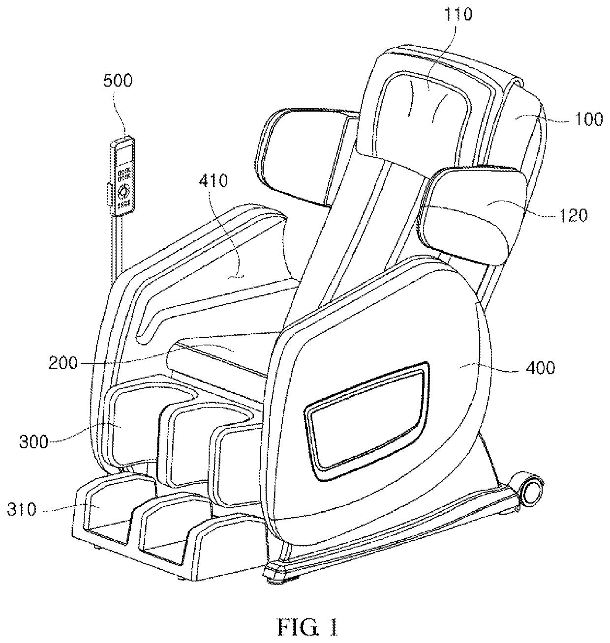
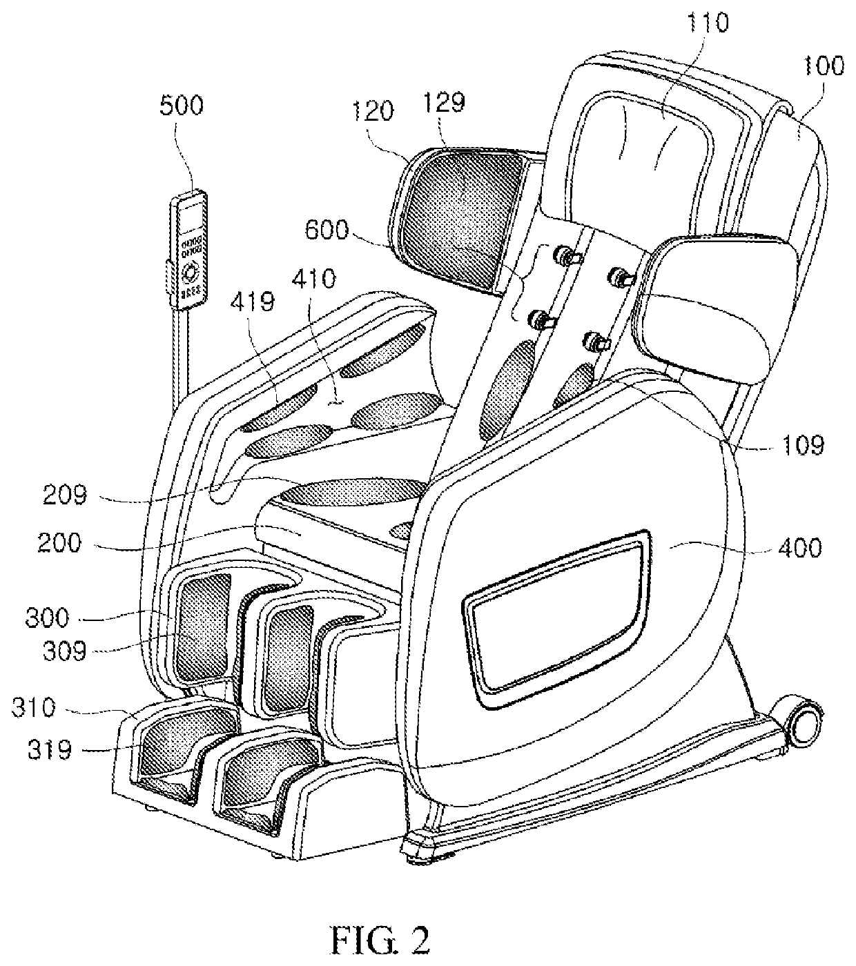
Heating assembly for massage chair including separate heating element and massage chair comprising the same
a heating element and massage chair technology, applied in massage, physical therapy, chiropractic devices, etc., can solve the problems of reducing the durability of the bracket, and reducing the heat transfer rate of the bracket, so as to prevent the phenomenon of excessive heat up of the bracket, the structure of the massage ball and the heating element can be simplified, and the effect of reducing the heat transfer ra
- Summary
- Abstract
- Description
- Claims
- Application Information
AI Technical Summary
Benefits of technology
Problems solved by technology
Method used
Image

Examples
first embodiment
Description of Heating Assembly
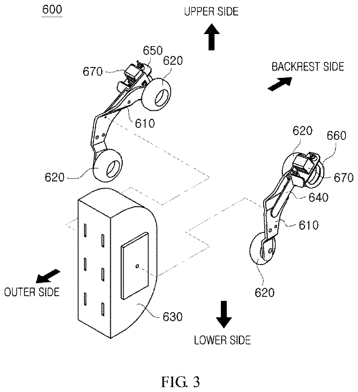
[0096]One of the distinguishing features of the heat generating assembly 600 according to the first embodiment of the present invention from the related art is that the heating element 660 is driven independently from the massage ball 620 so that the user is provided with a sense of warmth and a massaging feeling by the heating element 660 without the massage ball 620 being moved or heated.
[0097]In the massage chair according to the related art, in order to simultaneously provide the massaging feeling and the sense of warmth to the user, the massage ball contacting the user's back or shoulder need to be rotated and heated simultaneously, which was confirmed as the problem of the related art by the present inventors.
[0098]Thus, with the heating assembly 600 according to the first embodiment of the present invention, the massage ball 620 is not heated, but only rotated and moved up and down or left and right.
[0099]A second bracket 640 provided with the s...
PUM
 Abstract
Description
Claims
Application Information