
Low friction loss automatic transmission

a technology of automatic transmission and low friction loss, which is applied in the direction of mechanical equipment, transportation and packaging, and machining, etc., can solve the problems of low transmission efficiency, low friction loss of engine power, and remarkable friction loss of automatic transmission, so as to reduce the number of frictional elements (or clutches) and reduce the friction loss of the transmission

Inactive Publication Date: 2012-01-05
JATCO LTD +1
View PDF6 Cites 9 Cited by
  • Summary
  • Abstract
  • Description
  • Claims
  • Application Information

AI Technical Summary

Benefits of technology

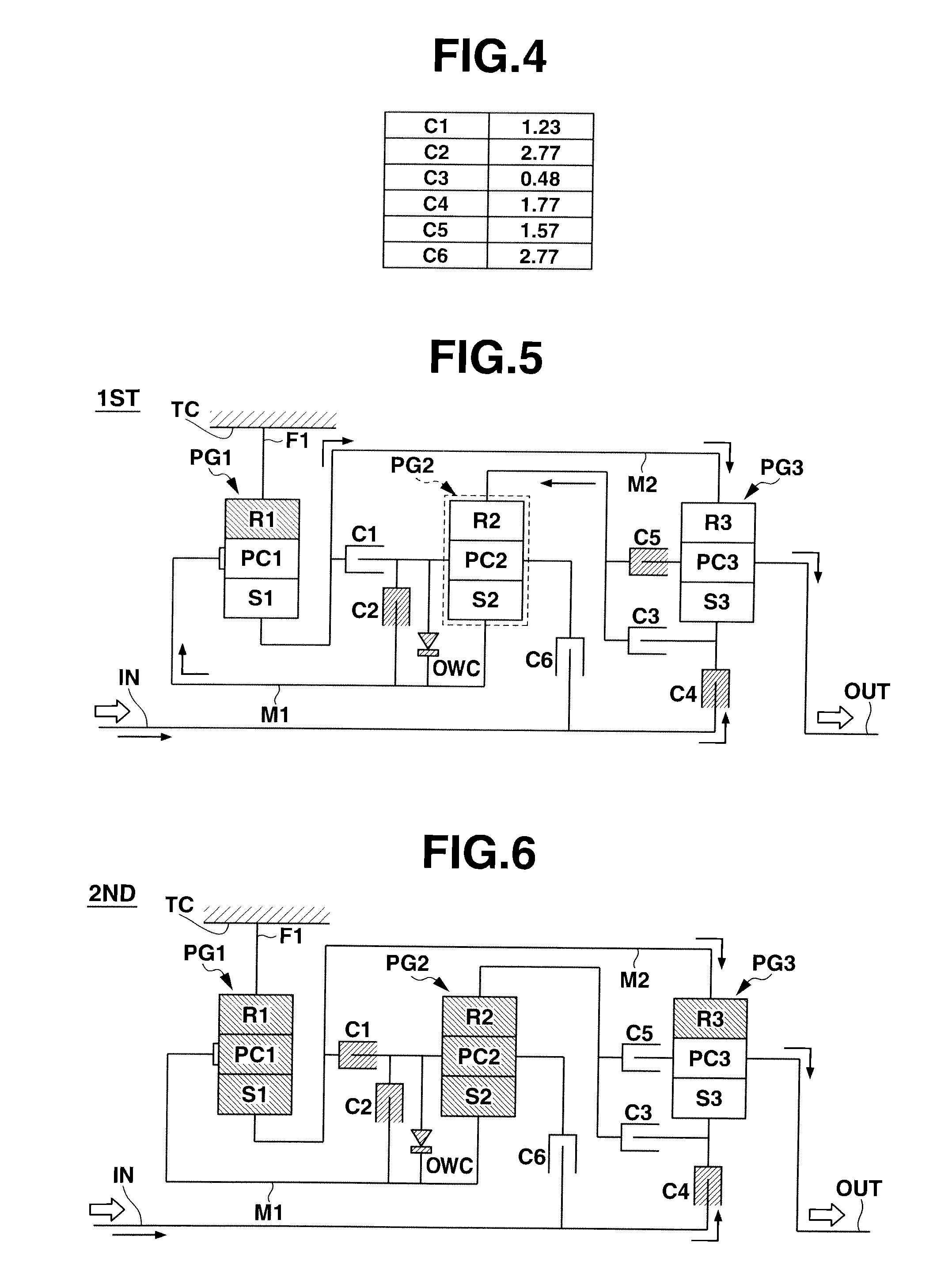
[0005]In the automatic transmission disclosed by the above-mentioned Japanese Laid-open Patent Application, each forward speed is established by putting selected two of the six frictional elements into their engaged condition. This means that under each forward speed, remaining four frictional elements are in their idling condition, which, for the following reasons, brings about a remarkable friction loss caused by oil churned by the remaining four idling frictional elements. As is known, such friction loss lowers a transfer efficiency of power from the engine to driven road wheels of an associated motor vehicle.
[0006]That is, in multi-plate type clutches and brakes that are widely used as the frictional elements of automatic transmissions, oil fed to the clutches and brakes for cooling and lubricating the same causes production of so-called oil dragging resistance (or resistance against oil shearing) when the clutches or brakes are in their idling condition. That is, during idling condition, the oil fed between mutually rotatable friction plates of each of the idling clutches or brakes is inevitably churned or stirred by the same thereby causing production of a considerable resistance (viz., oil dragging resistance) against rotation of a temporarily united train of parts that contributes to establish a desired speed, which however increases a friction loss of the automatic transmission.
[0007]Thus, an object of the present invention is to provide a stepwisely variable automatic transmission which comprises three planetary gear units and six frictional elements and establishes at least eight forward speeds while avoiding the above-mentioned remarkable friction loss.
[0008]That is, in the stepwisely variable automatic transmission of the present invention, the friction loss produced at each speed is reduced or at least minimized for increasing the transfer efficiency of power from the engine to the driven road wheels.
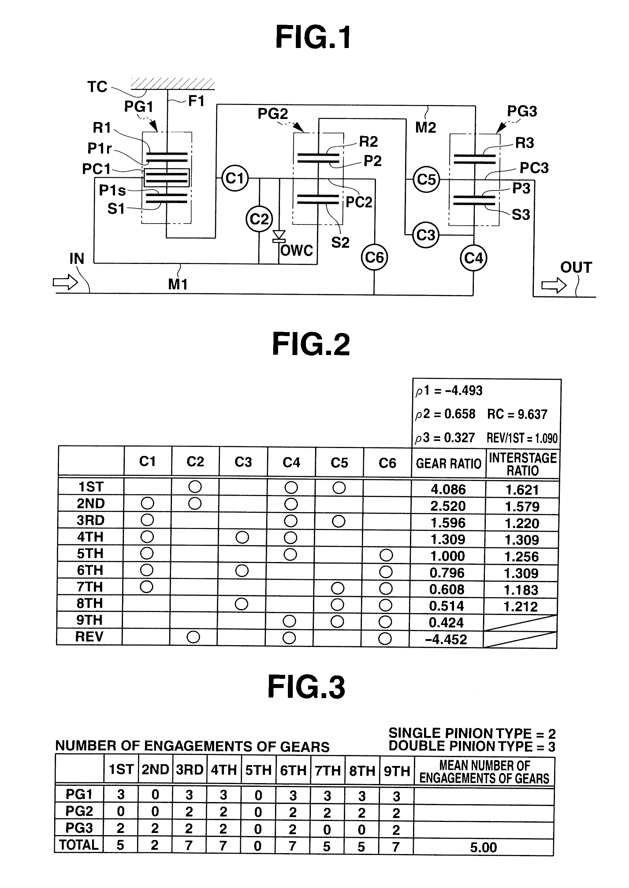
[0013]As is understood from the above, in the automatic transmission of the present invention, each speed is established by simultaneously putting selected three of the six frictional elements (or clutches) into their engaged condition leaving the remaining three frictional elements (or clutches) in their idling condition. Reduction in number of the frictional elements (or clutches) that are idle at each established speed brings about reduction in friction loss of the transmission.

Problems solved by technology

This means that under each forward speed, remaining four frictional elements are in their idling condition, which, for the following reasons, brings about a remarkable friction loss caused by oil churned by the remaining four idling frictional elements.
As is known, such friction loss lowers a transfer efficiency of power from the engine to driven road wheels of an associated motor vehicle.
That is, during idling condition, the oil fed between mutually rotatable friction plates of each of the idling clutches or brakes is inevitably churned or stirred by the same thereby causing production of a considerable resistance (viz., oil dragging resistance) against rotation of a temporarily united train of parts that contributes to establish a desired speed, which however increases a friction loss of the automatic transmission.

Method used


Image

  • Low friction loss automatic transmission
  • Low friction loss automatic transmission
  • Low friction loss automatic transmission

Examples


Embodiment Construction

[0033]In the following, the stepwisely variable automatic transmission of the present invention will be described in detail with reference to the accompanying drawings.

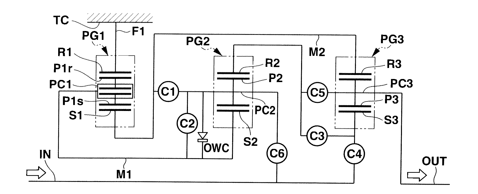
[0034]Referring to FIG. 1, there is schematically shown the stepwisely variable automatic transmission according to the present invention.

[0035]As shown in FIG. 1, the stepwisely variable automatic transmission generally comprises an input shaft IN, an output shaft OUT, a first planetary gear unit PG1, a second planetary gear unit PG2, a third planetary gear unit PG3, a first rotatable member M1, a second rotatable member M2, a first fixing member F1, a first clutch C1 (or first frictional element), a second clutch C2 (or second frictional element), a third clutch C3 (or third frictional element), a fourth clutch C4 (or fourth frictional element), a fifth clutch C5 (or fifth frictional element), a sixth clutch C6 (or sixth frictional element) and a transmission case TC.

[0036]The first planetary gear unit PG1 is of a d...


PUM


Abstract

An automatic transmission including a double pinion planetary gear unit PG1, two single pinion planetary gear units PG2 and PG3 and six frictional elements (viz., six clutches) C1 to C6 is so constructed as to establish nine forward speeds and one reverse speed by simultaneously putting selected three of the six frictional elements C1 to C6 into their engaged condition. The frictional elements C1 to C6 are of a type including mutually rotatable friction plates that cause production of an oil dragging resistance when the frictional element is under idling condition. With the simultaneously engaged condition of the three frictional elements, each speed is established with a reduced friction loss of the automatic transmission.

Description

BACKGROUND OF THE INVENTION[0001]1. Field of the Invention[0002]The present invention relates to stepwisely variable automatic transmissions of motor vehicles, and more particularly to the stepwisely variable automatic transmissions of a type that exhibits a reduced friction loss at each speed established.[0003]2. Description of the Related Art[0004]Japanese Laid-open Patent Application (Tokkai) 2001-182785 shows a stepwisely variable automatic transmission that establishes eight forward speeds and two reverse speeds by operating three planetary gear units and six frictional elements in a controlled manner. The three planetary gear units are a double pinion type planetary gear unit, a Ravigneaux-double pinion type planetary gear unit and a Ravigneaux-single pinion type planetary gear unit, and the six frictional elements are four clutches and two brakes.SUMMARY OF THE INVENTION[0005]In the automatic transmission disclosed by the above-mentioned Japanese Laid-open Patent Application,...

Claims


Application Information

Patent Timeline
IPC IPC(8): F16H3/62
CPCF16H3/666F16H2003/445F16H2200/0065F16H2200/2082F16H2200/2046F16H2200/2048F16H2200/2097F16H2200/201F16H3/62F16H3/66
Inventor AOTA, KAZUAKIINUTA, YUKIYOSHIYAMAMOTO, AKIHIROOKUDA, TAKAYUKI
Owner JATCO LTD
Learn More