Failure diagnostic system, electronic control unit for vehicle, failure diagnostic method

a failure diagnostic and electronic control technology, applied in the field of failure diagnostic system, electronic control unit for vehicle, failure diagnostic method, can solve problems such as affecting reducing the execution speed of standard processing with respect, and abnormal detection

Active Publication Date: 2012-01-05
TOYOTA JIDOSHA KK
View PDF6 Cites 21 Cited by
  • Summary
  • Abstract
  • Description
  • Claims
  • Application Information

AI Technical Summary

Benefits of technology

[0009]The invention provides a failure diagnostic system that may specify a CPU core in which an abnormality has occurred from among a plurality of CPU cores, without affecting the execution speed of standard processing, and also an ECU for a vehicle and a failure diagnostic method.

Problems solved by technology

Further, in a multicore processor in which one microcomputer carries a plurality of CPU cores, an abnormality is detected by executing the same processing in a plurality of CPU and comparing the processing results.
However, executing the same processing in a plurality of CPU or executing a certain instruction for abnormality detection, as shown in FIG. 14, may put pressure upon resources of the microcomputer or processor, thereby affecting the execution speed of standard processing (reducing the execution speed of standard processing with respect to the usual one) such as control or data processing that is essentially required for the processor.
However, the OS disclosed in the JP-A-2008-123439 is not different from that disclosed in JP-A-7-230392 in that a pressure is put upon the resources of microcomputer or processor, for example, a “1+1” addition” is performed by a CPU core, when an abnormality is detected and, therefore, the execution speed of standard processing may be affected.

Method used


Image

  • Failure diagnostic system, electronic control unit for vehicle, failure diagnostic method
  • Failure diagnostic system, electronic control unit for vehicle, failure diagnostic method
  • Failure diagnostic system, electronic control unit for vehicle, failure diagnostic method

Examples


second embodiment

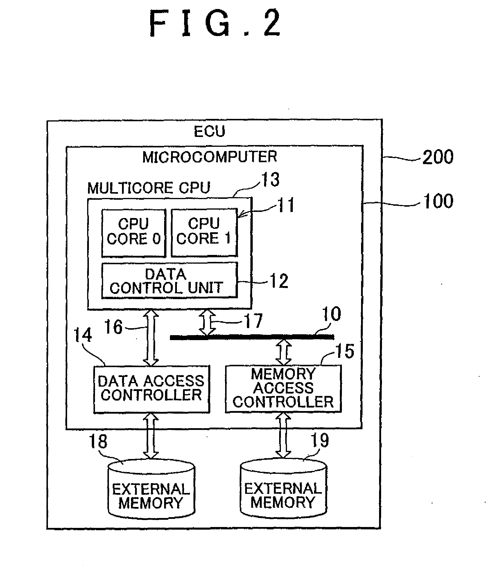
[0050]The second embodiment will be explained below. In FIG. 2, a microcomputer 100 has the multicore CPU 13, a data access controller 14, a memory access controller 15, and data buses 16, 17. The multicore CPU 13 has a CPU core 0, a CPU core 1, and a data control unit 12. The data access controller 14 is connected to an external memory 18, and the memory access controller 15 is connected to the external memory 19. The multicore CPU 13 may be installed at an LSI, rather than the microcomputer 100.

[0051]An Electronic Control Unit (ECU) 200 installed at a vehicle may be realized by the microcomputer 100, external memory 18, and external memory 19. For example, in the ECU 200 of a multimedia system, the processing of displaying a road map on a display device on the basis of position information detected by a global positioning system (GPS) receiver and searching a route to the destination, video processing of television or camera images, and voice processing or radio or CD player are t...

fourth embodiment

[0105]In the configuration shown in FIG. 2, the external memory 18 is externally attached to the microcomputer 100, but the external memory 18 may be also provided inside the microcomputer 100. FIG. 13 shows an example of a block-diagram of the microcomputer 100 of the fourth embodiment in which the external memory 18 is provided in the data control unit 12. In FIG. 13, the components identical to those shown in FIG. 2 are assigned with same reference numerals and explanation thereof is herein omitted. The test data 37 may be the same, regardless of the passage of time, and where the test data 37 are not changed, the expected value also may be the same.

[0106]Therefore, the external memory may thus be incorporated in the data control unit 12. In this case, it is not necessary for the data access controller 14 to read the test data 37 and expected values from the external memory 18, and the failure diagnostic time may be shortened. The external memory 18 incorporated in the data contr...


PUM


Abstract

A failure diagnostic system (100) for a multicore CPU having installed therein a plurality of CPU cores (11) that is configured to be switched from a SMP mode to an AMP mode includes: load prediction means for predicting a processing load of the multicore CPU; mode switching means for switching at least one of the CPU cores (11) to the AMP mode when the processing load is less than a threshold; and failure diagnostic means for performing a failure diagnosis of the CPU core that has been switched to the AMP mode.

Description

BACKGROUND OF THE INVENTION[0001]1. Field of the Invention[0002]The invention relates to a failure diagnostic system for a multicore central processing unit (CPU) that is provided with a plurality of CPU cores, and more particularly to a failure diagnostic system that performs a failure diagnosis of each CPU core individually, an electronic control unit (ECU) for a vehicle, and a failure diagnostic method.[0003]2. Description of the Related Art[0004]Mutual abnormality detection is sometimes conducted by detecting abnormality in a LSI or microcomputer by using a configuration in which a plurality of LSI or microcomputers are installed in one system and monitoring a watchdog signal transmitted from one large scale integration (LSI) (microcomputer) to another LSI (microcomputer). Further, in a multicore processor in which one microcomputer carries a plurality of CPU cores, an abnormality is detected by executing the same processing in a plurality of CPU and comparing the processing res...

Claims


Application Information

Patent Timeline
Patent Type & Authority Applications(United States)
IPC IPC(8): G06F11/07
CPCG06F11/0751G06F11/0724G06F11/2242G06F11/1428
Inventor SHIGEHARA, EIICHIRO
Owner TOYOTA JIDOSHA KK
Why Eureka
Try Eureka