Custom Made Cuff LInks and Method for Making the Same

a cuff link and custom technology, applied in the field of custom made cuff links, can solve the problems of few choices, if any, in regard to cuff links

Inactive Publication Date: 2012-01-12
SEVERYN MARK RODNEY
View PDF18 Cites 14 Cited by
  • Summary
  • Abstract
  • Description
  • Claims
  • Application Information

AI Technical Summary

Benefits of technology

[0009]The present invention provides a custom made cuff link structure and a method for making the same that allows for the use of a cuff link in conjunction with both shirts that have cuffs specifically designed to receive cuff links and shirts that are designed with simple button and button hole cuffs. The present invention describes the use of ordinary buttons or other toggles and clothing accessories that are modified to incorporate looped strands of a clear polymer fiber or fibers in a manner that allows the retention of the button like component on the cuff of the shirt through the process of looping the polymer fiber back over the button like object or over existing buttons positioned on the cuff. A first embodiment of the present invention allows the manufacture of customized cuff links utilizing polymer based fibers and button like objects selected by the maker. A second embodiment utilizes factory made cuff links that incorporate the same basic design as the custom made cuff links of the first embodiment. Use of the cuff links may be carried out in conjunction with standard cuffs designed for use with cuff links whereby two button holes may be used to secure the looped around polymer fiber, or more practically for use in conjunction with shirt cuffs not specifically intended for cuff links, whereby a hidden button may be used in conjunction with the looped polymer fiber.

Problems solved by technology

In addition, there are few, if any, choices with regard to the manner of altering a cuff that has not been structured to receive a cuff link so as to easily and securely receive the cuff link without disrupting or destroying the design of the shirt.

Method used


Image

  • Custom Made Cuff LInks and Method for Making the Same
  • Custom Made Cuff LInks and Method for Making the Same
  • Custom Made Cuff LInks and Method for Making the Same

Examples


Embodiment Construction

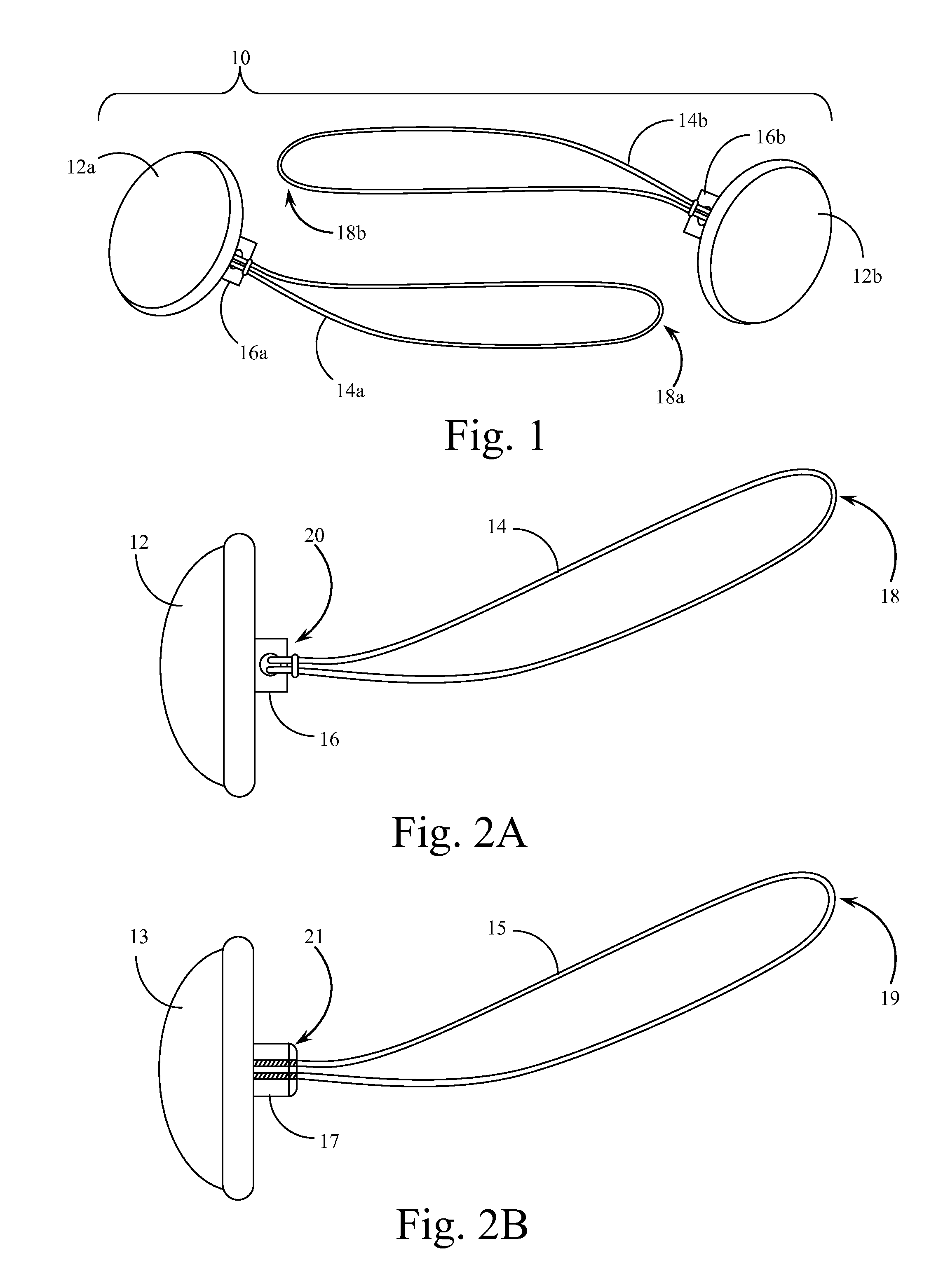
[0018]Reference is made first to FIG. 1 which is a perspective view of the custom made cuff links of the present invention showing a completed pair of cuff links. Custom made cuff link pair 10 is shown to be configured from button like components 12a and 12b which may be any of a number of different buttons or other such objects selected by the maker of the cuff link pair. The present invention is intended to accommodate a wide variety of buttons and button like objects and to most easily accommodate buttons of the type that have an aperture through which the monofilament line component of the present invention may extend. In FIG. 1 monofilament line components 14a and 14b are shown to each extend from button attachment posts 16a and 16b. The monofilament line components 14a and 14b from monofilament line loop ends 18a and 18b which, in the preferred embodiment, may be a single closed loop of clear polymer fiber attached back on itself to form a loop. Alternately, components 14a and...


PUM

PropertyMeasurementUnit
lengthaaaaaaaaaa
cut lengthaaaaaaaaaa
distanceaaaaaaaaaa

Abstract

A custom cuff link structure and a method for making the same that allows for the use of the cuff link with both shirts that have cuffs specifically designed to receive cuff links and shirts that are designed with simple button and buttonhole cuffs. The structure and method use ordinary buttons or other toggles and clothing accessories that are modified to incorporate looped strands of a clear polymer fiber to allow the retention of the button like component on the cuff of the shirt. A first embodiment allows the manufacture of customized cuff links utilizing polymer based fibers or button like objects selected by the maker. A second embodiment anticipates factory made cuff links that incorporate the same basic design. Use of the cuff links may be in conjunction with shirt cuffs not specifically intended for use with cuff links, whereby a hidden button may be connected with the looped polymer fiber.

Description

CROSS REFERENCES TO RELATED APPLICATIONS[0001]This application claims the benefit under Title 35 United States Code §119(e) of U.S. Provisional Application 61 / 363,156 filed Jul. 9, 2010, the full disclosure of which is incorporated herein by reference.BACKGROUND OF THE INVENTION[0002]1. Field of the Invention[0003]The present invention relates generally to clothing accessories, particularly for men. The present invention relates more specifically to devices for securing the cuffs of long-sleeved shirts in both a functional and decorative manner.[0004]2. Description of the Related Art[0005]Many efforts have been made in the past to provide both functional and decorative designs for cuff links and other methods for securing the cuffs of long-sleeved shirts, especially those worn by men. The standard cuff link is a generally solid object, typically in the form of a large button or the like, from which extends a short post, typically with a hinged member that may be inserted through but...

Claims


Application Information

Patent Timeline
Patent Type & Authority Applications(United States)
IPC IPC(8): A44B5/02A44C27/00
CPCA44B5/00Y10T29/4959Y10T24/364A44B5/007
Inventor SEVERYN, MARK RODNEY
Owner SEVERYN MARK RODNEY
Why Eureka
Try Eureka