Optical system with automatic switching between operation in daylight and thermovision modes

an optical system and automatic switching technology, applied in the field of optical sight systems, can solve the problems of heavy weight, inability to use in a stand-alone state, and inconvenient use in combat conditions

Inactive Publication Date: 2012-01-12
AMERICAN TECH NETWORK
View PDF16 Cites 59 Cited by
  • Summary
  • Abstract
  • Description
  • Claims
  • Application Information

AI Technical Summary

Benefits of technology

[0022]Since the CCD attachment is small and lightweight, it can be disconnected from the thermal scope and stored in a convenient location, e.g., in a pocket. In that case the thermal scope operates in its conventional night-vision mode. When necessary, the CCD attachment can be momentarily attached to the thermal scope through the quick-release connection unit, and the device will operate with automatic switching between daylight visual mode and night thermal-vision mode, depending on the brightness of the visual signal obtained by the comparator.

Problems solved by technology

Some of them are large, cumbersome, or cannot be used in a stand-alone state, and therefore they are heavy in weight and unsuitable for use in combat conditions.

Method used


Image

  • Optical system with automatic switching between operation in daylight and thermovision modes
  • Optical system with automatic switching between operation in daylight and thermovision modes
  • Optical system with automatic switching between operation in daylight and thermovision modes

Examples


Embodiment Construction

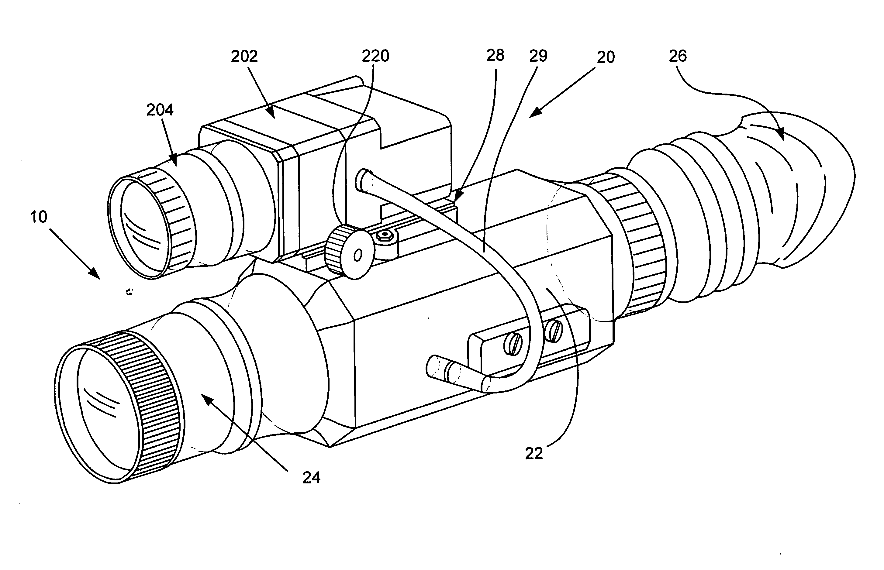
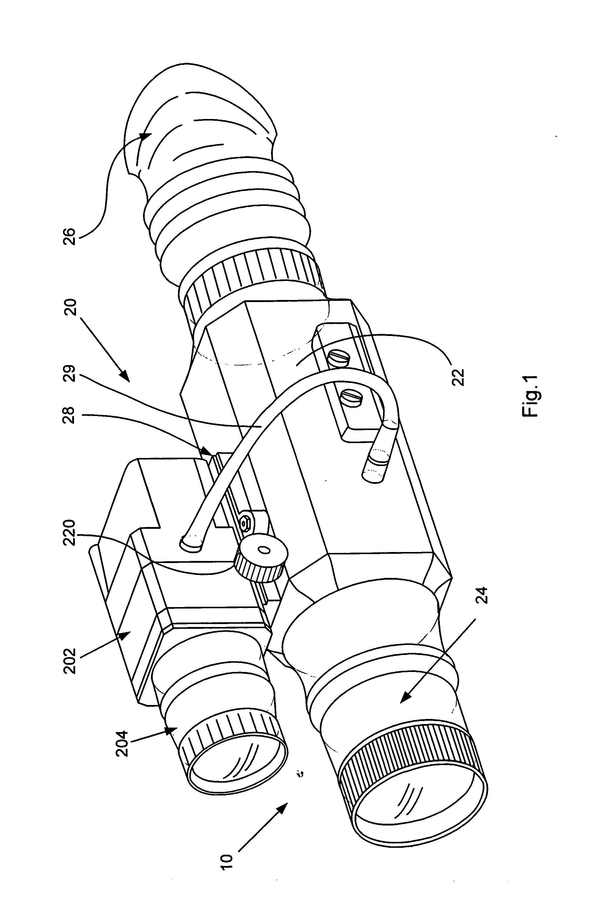
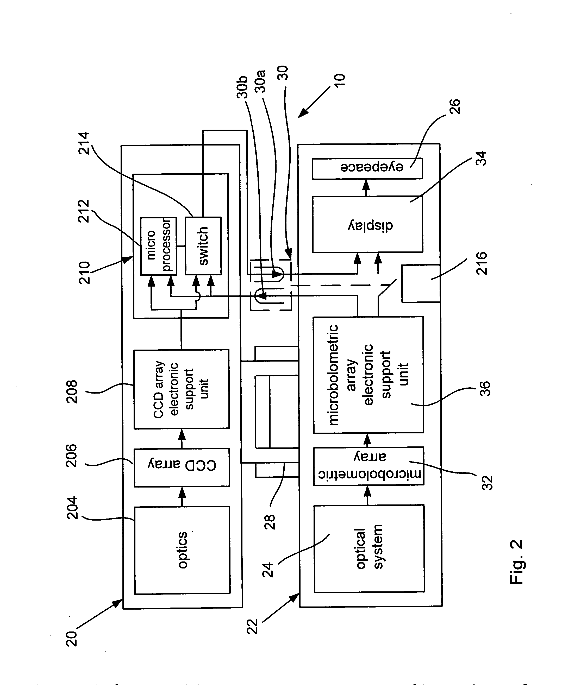
[0024]A general three-dimensional view of an optical sight system that comprises a thermal scope and a CCD visual-range attachment is shown in FIG. 1, and a block diagram of the system is shown in FIG. 2. As shown in the drawings, the system, which as a whole is designated by reference numeral 10, comprises a thermal scope 20 and a CCD visual-range attachment 200 with automatic switching between operational modes (i.e., the day-light visual mode or a night-vision thermal-vision mode). Although in the illustrated example the system 10 composed of the thermal scope 20 and a CCD visual-range attachment 200 is shown as an optical sight, other applications such as spotting scopes, binoculars, or the like, are also possible. In other words, the specific example of the optical sight is further described only for illustrative purposes.

[0025]The main part of the system 10 is a thermal scope 20, which may comprise a conventional optical-sight type of thermal scope that operates in the wavelen...


PUM


Abstract

An optical sight system that comprises a combination of a thermal scope with a CCD visual-range attachment connectable to the thermal scope with a quick-release connector. The system is equipped with a device that automatically activates the CCD visual-range attachment when the latter is connected to the thermal scope and with a comparator that compares the video signal of the CCD attachment with the video signal of the thermal scope for sending the brightest video signal to the thermal scope display.

Description

FIELD OF THE INVENTION[0001]The present invention relates to an optical system that comprises a charge coupled camera (CCD) camera and a thermal scope. More specifically, the invention relates to an optical sight system composed of a thermal scope and a CCD visual-range attachment with automatic switching between the daylight operation mode and the night thermal-vision mode. The optical sight system of the invention is intended for use on a firearm weapon as well as on spotting scopes, binoculars, etc.BACKGROUND OF THE INVENTION[0002]Known in the art is a great variety of optical sights, which, according to one variety of classifications, is categorized according to three ranges of operational wavelength: (1) day-vision optical sights; (2) night-vision optical sights; and (3) thermal-vision sights. Daylight optical sights operate in the wavelength range of 400 nm to 700 nm. Night-vision optical sights operate in the wavelength range of near infrared light to 1.7 nm. Thermal-vision s...

Claims


Application Information

Patent Timeline
Patent Type & Authority Applications(United States)
IPC IPC(8): H04N9/68H04N5/33
CPCH04N5/332H04N23/11
Inventor GABER, LEONID
Owner AMERICAN TECH NETWORK
Why Eureka
Try Eureka