Antenna controller device, radio communication system, and antenna controlling method

a technology of antenna controller and radio communication system, which is applied in the direction of antennas, diversity/multi-antenna systems, spatial transmit diversity, etc., can solve the problem of not being able to offer a high-quality communication service to the radio terminal, and achieve the effect of high-quality communication servi

Inactive Publication Date: 2012-01-19
KYOCERA CORP
View PDF5 Cites 23 Cited by
  • Summary
  • Abstract
  • Description
  • Claims
  • Application Information

AI Technical Summary

Benefits of technology

[0024]According to the present invention, there are provided an antenna controller device, a radio communication system, and an antenna controlling method which are capable of appropriately setting a tilt angle and offering a high quality communication service to radio terminals even when a base station antenna is installed in a low-altitude position and the radio terminals are spread over in a height direction.

Problems solved by technology

However, the conventional beam tilt technique adjusts the tilt angle only within an angle range on the depression side by using the amount of interfering and the like based on the design of area-wide communication area, and therefore has a problem of being incapable of offering a high quality communication service to the radio terminals spread over in the height direction.

Method used


Image

  • Antenna controller device, radio communication system, and antenna controlling method
  • Antenna controller device, radio communication system, and antenna controlling method
  • Antenna controller device, radio communication system, and antenna controlling method

Examples


first embodiment

(Modification of First Embodiment)

[0079]FIG. 7 is a block diagram showing a configuration of the radio base station 100A according to a modification of the first embodiment

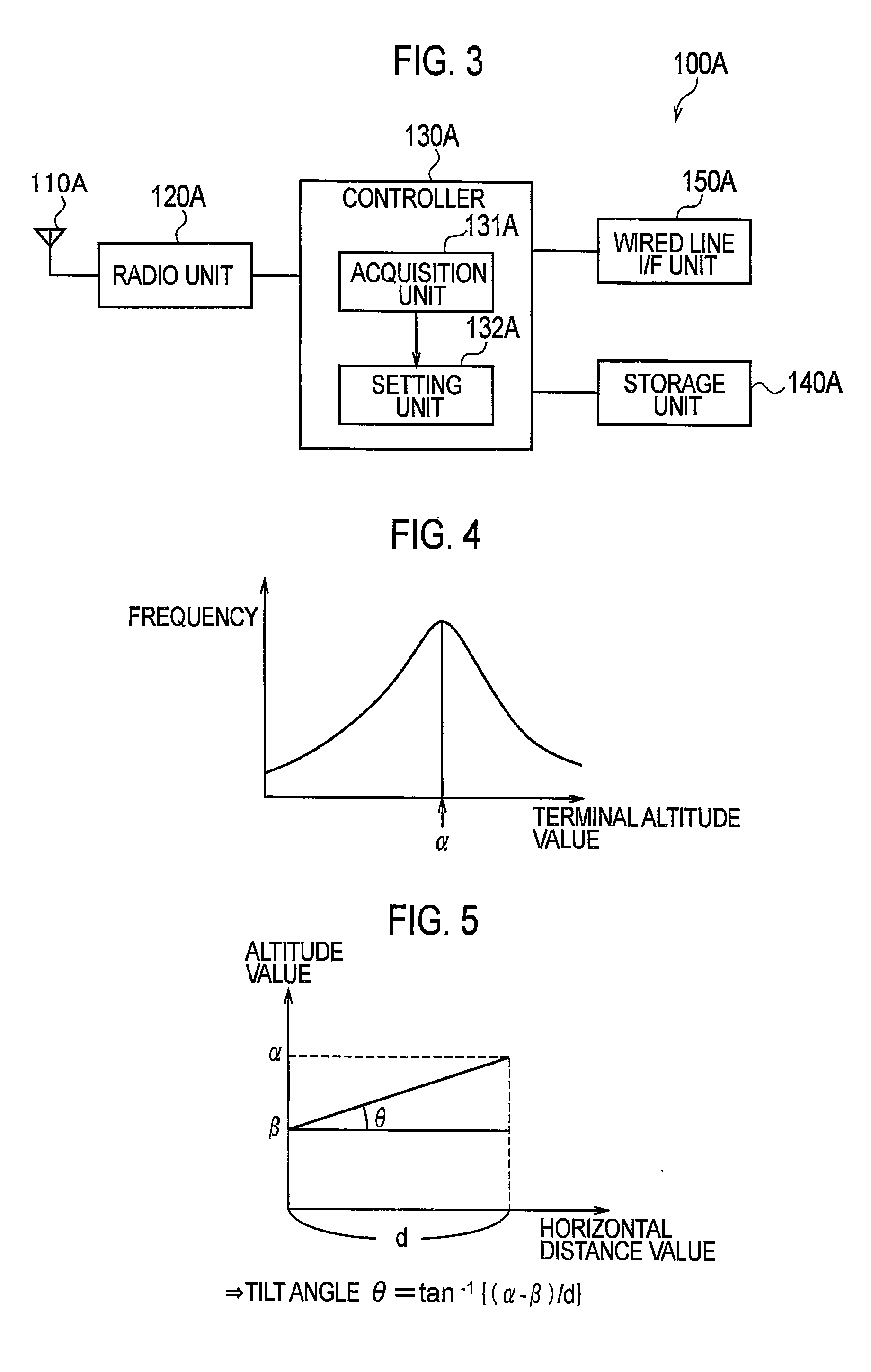
[0080]The directional antenna 110A is provided integrally with the body of the radio base station 100A in the first embodiment whereas the directional antenna 110A is provided separately from the body of the radio base station 100A in this modification. For example, the radio unit 120A and the control unit 130A of the radio base station 100A is connected to each other via an optical fiber line or the like. As for the above-described interface, it is possible to use an established standard such as CPRI (Common Public Radio Interface).

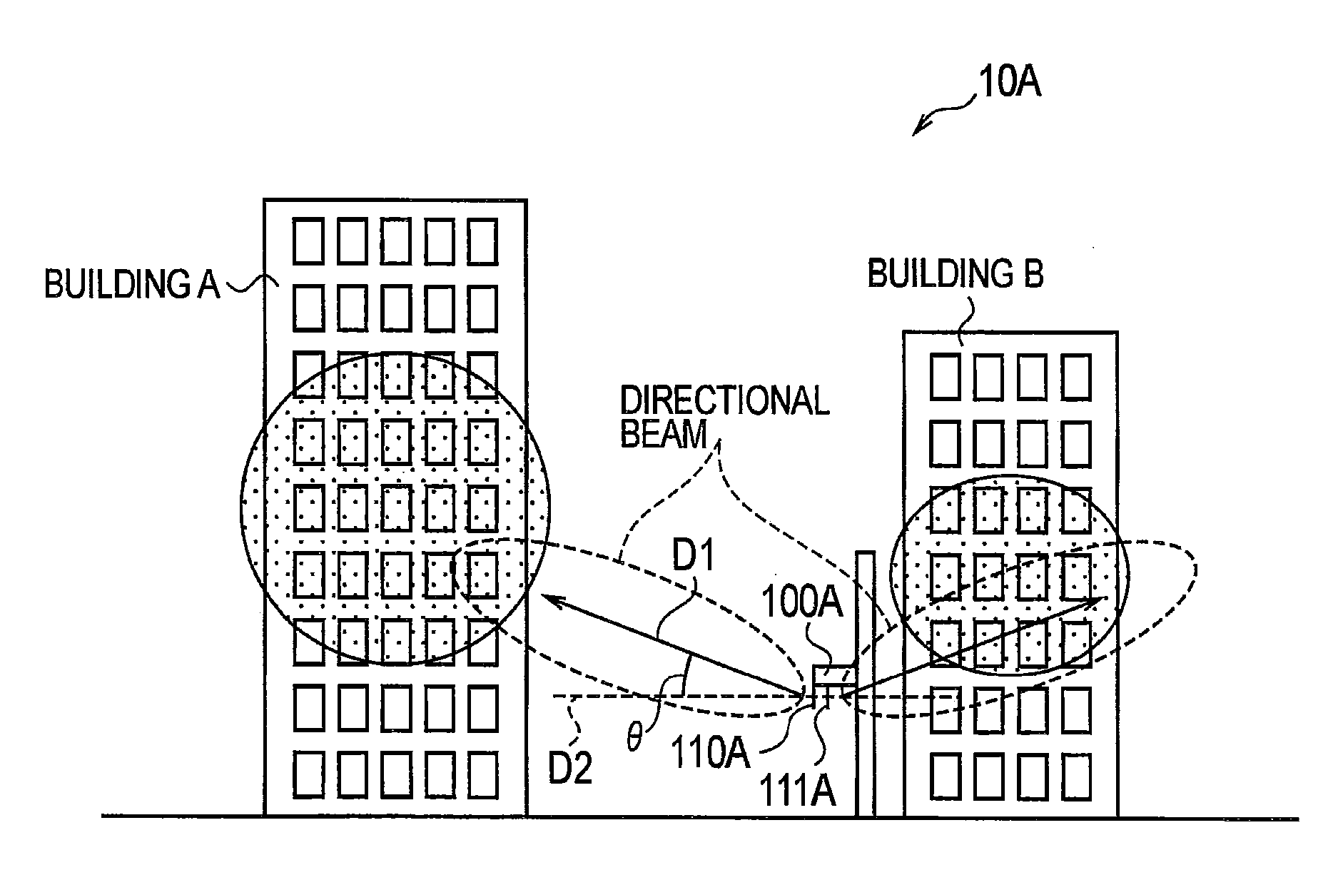
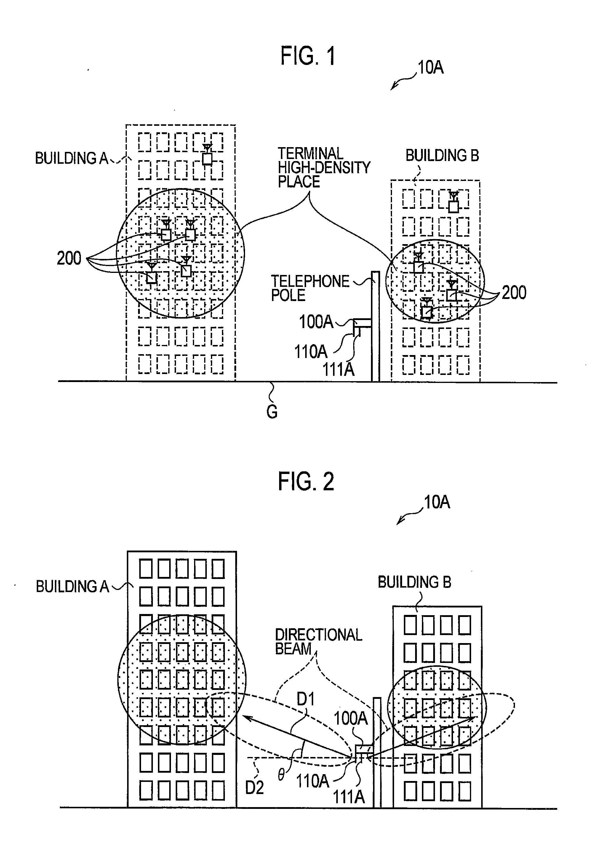
[0081]In the installation example as shown in FIG. 1, there may be a case where it is difficult to install the entire radio base station 100A on the telephone pole. In such a case, it is conceivable to install a radio instrument (RE) provided with the directional antenna 110A and the r...

second embodiment

(Modification of Second Embodiment)

[0092]FIG. 11 is a block diagram showing a configuration of the radio base station 100A according to a modification of the second embodiment. This modification is a mode in which the above-described modification of the first embodiment and the second embodiment are combined.

[0093]In the example of FIG. 8 and FIG. 9, the radio base station 100A and the radio base station 100B are installed separately in the height direction. Meanwhile, in this modification, it is possible to install the directional antenna 110A and the directional antenna 110B of the same radio base station 100A separately in the height direction. For example, the directional antenna 110A shown in FIG. 11A is installed on the telephone pole similarly to the FIG. 8 and FIG. 9 while the directional antenna 110B shown in FIG. 11 is installed on the wall face of the building B similarly to FIG. 8 and FIG. 9.

[0094]The setting unit of the radio base station 100A sets the respective tilt a...

third embodiment

[0095]A third embodiment provides a mode in which a tilt angle is set in an upper network apparatus. In the third embodiment, only different features from those of the first embodiment and the second embodiment will be described and duplicate explanation will be omitted.

[0096]FIG. 12 is a schematic configuration diagram of a radio communication system 10C according to the third embodiment. In the radio communication system 10C, the radio base station 100A and the radio base station 100B are each configured as in the second embodiment. However, the radio communication system 10C is different from the second embodiment in that a base station controller 300 is provided for controlling the radio base station 100A and the radio base station 100B. The base station controller 300 is connected to the radio base station 100A and the radio base station 100B via a wired line (a backhaul network). For the base station controller 300 described above, it is possible to use an EMS (Element Managem...


PUM


Abstract

A radio base station (100A) has a directional antenna (110A) by which the beam direction (D1) which is a direction to which a directional beam is directed can be changed in a vertical plane. The radio base station (100A) acquires a terminal altitude value indicating the altitude of a radio terminal connected to the radio base station (100A), and sets a tilt angle (θ) which is an angle made by the beam direction (D1) and the horizontal direction by use of the acquired terminal altitude value.

Description

TECHNICAL FIELD[0001]The present invention relates to an antenna controller device, a radio communication system, and an antenna controlling method for controlling an antenna unit capable of changing a beam direction in a vertical plane, the beam direction being a direction to which a directional beam is directed.BACKGROUND ART[0002]Conventionally, cellular radio communication systems (hereinafter, cellular system) has achieves an area-wide coverage of a wide service area by dividing the wide service area into units of communication areas called cells and by equipping the communication areas with radio base stations in charge of radio communications with radio terminals in their respective communication areas.[0003]In order to expand the communication area of a radio base station, it is effective to install an antenna unit of the radio base station (hereinafter a base station antenna) at a high position. For this reason, in the conventional cellular system, the base station antennas...

Claims


Application Information

Patent Timeline
Patent Type & Authority Applications(United States)
IPC IPC(8): H04W16/28H01Q3/02
CPCH04B7/0617H04B7/028
Inventor NOJI, MASAKI
Owner KYOCERA CORP
Why Eureka
Try Eureka