Supercharge Your Innovation With Domain-Expert AI Agents!

Drop and slide mechanism for use with dunnage conversion machine and method

a dunnage and conversion machine technology, applied in the field of dunnage conversion machines, can solve the problems of difficult or time-consuming for packers to replenish the supply, difficult access to the conversion machine and/or stock material supply to inspect and repair the machine, or to replenish the supply of stock material, etc., to achieve the effect of convenient access to an elevated dunnage conversion machin

Active Publication Date: 2012-01-19
RANPAK CORP
View PDF33 Cites 14 Cited by
  • Summary
  • Abstract
  • Description
  • Claims
  • Application Information

AI Technical Summary

Benefits of technology

[0005]When the supply of stock material is located on an opposite side of the work surface from the packer, it can be difficult or time-consuming for the packer to replenish the supply. When a dunnage conversion machine or a supply of stock material are mounted above the work surface, the elevated position can make it difficult to access the conversion machine and / or stock material supply to inspect and repair the machine or to replenish the supply of stock material. The invention described in the following paragraphs makes it easier to access an elevated dunnage conversion machine or supply of stock material.

Problems solved by technology

When the supply of stock material is located on an opposite side of the work surface from the packer, it can be difficult or time-consuming for the packer to replenish the supply.
When a dunnage conversion machine or a supply of stock material are mounted above the work surface, the elevated position can make it difficult to access the conversion machine and / or stock material supply to inspect and repair the machine or to replenish the supply of stock material.

Method used


Image

  • Drop and slide mechanism for use with dunnage conversion machine and method
  • Drop and slide mechanism for use with dunnage conversion machine and method
  • Drop and slide mechanism for use with dunnage conversion machine and method

Examples


Embodiment Construction

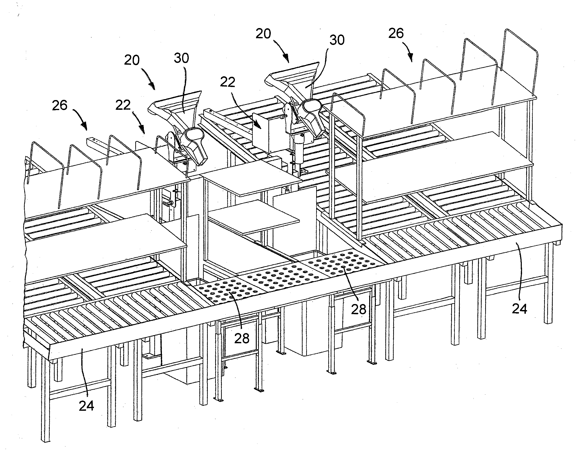
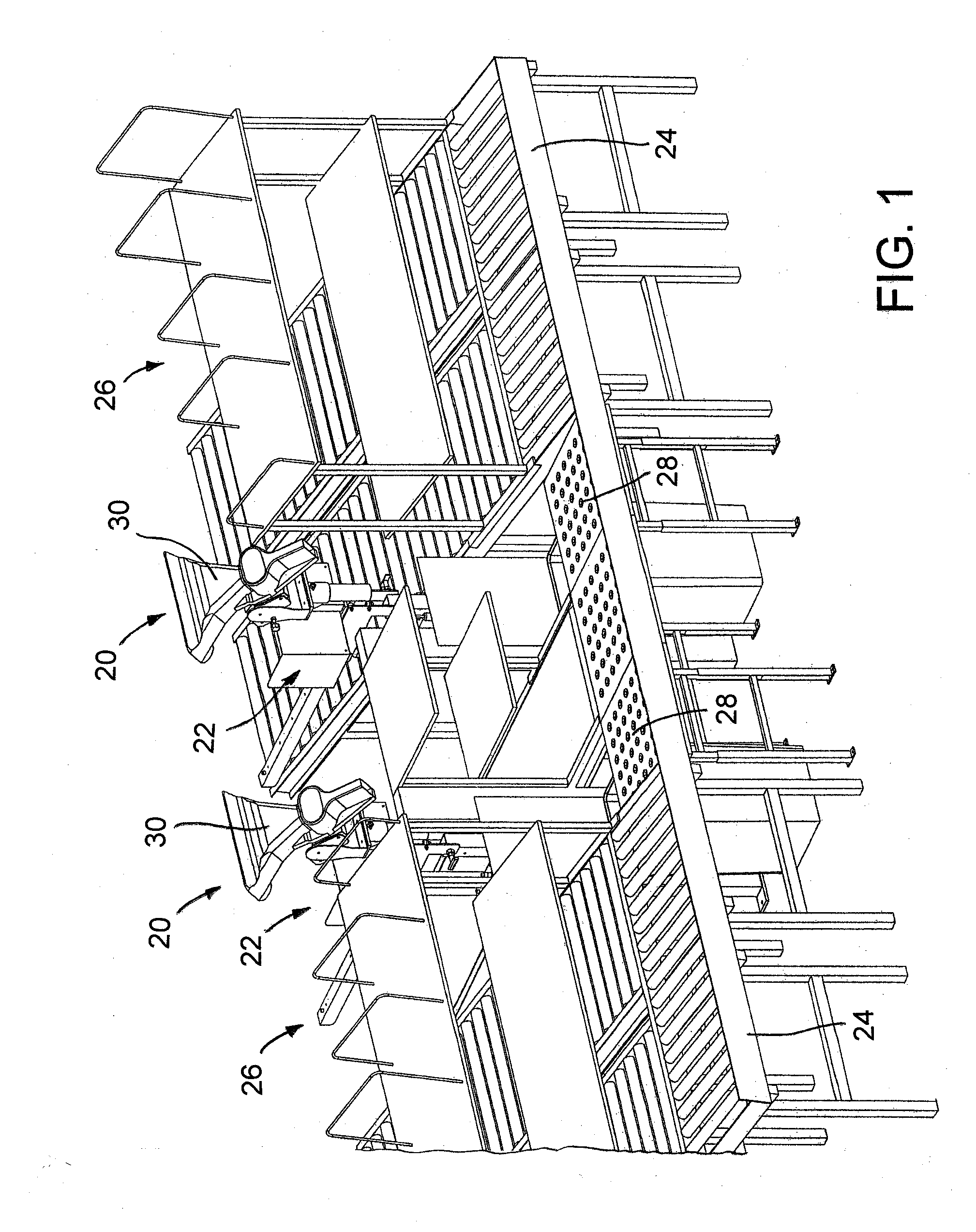
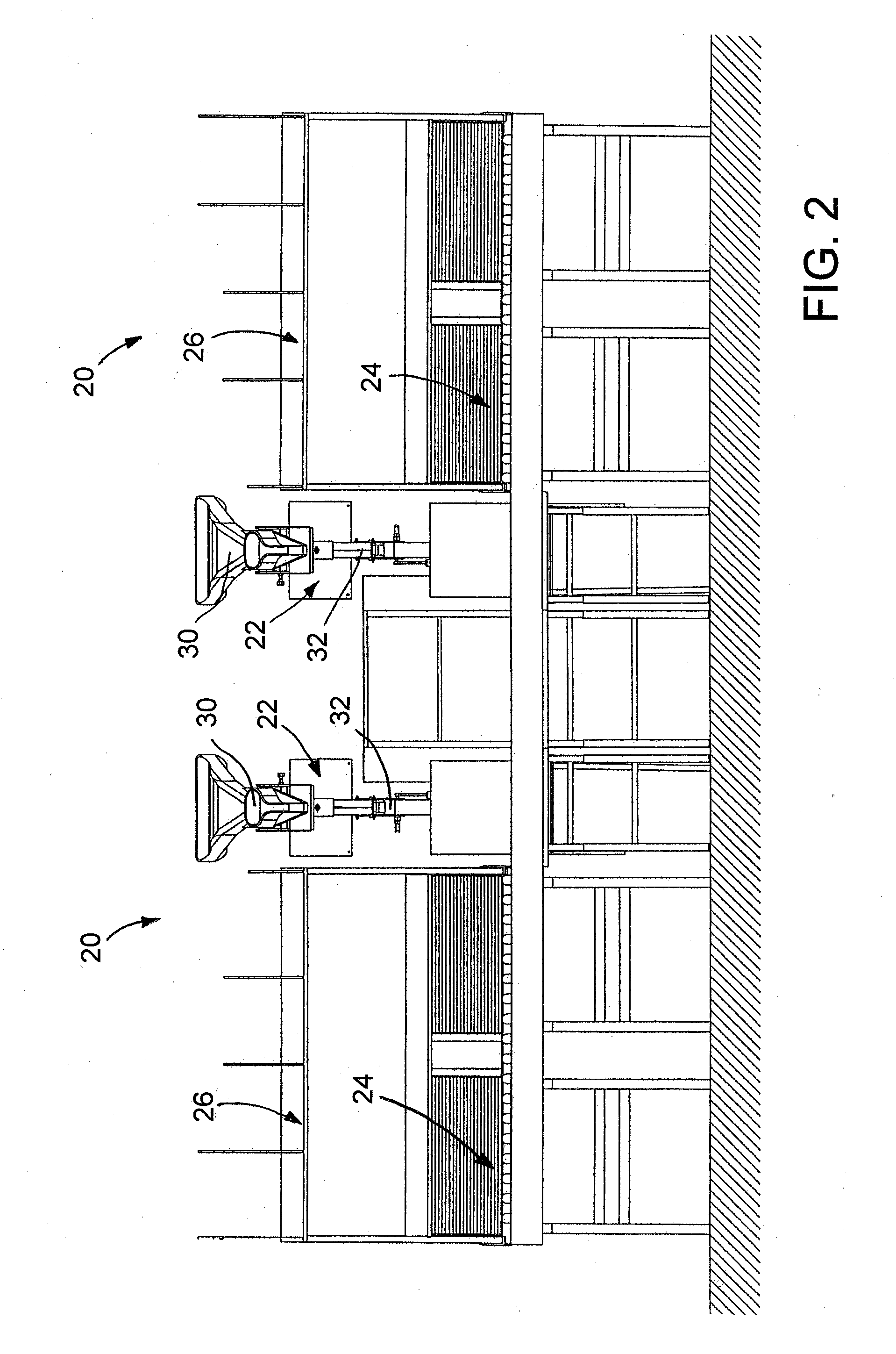
[0023]The present invention provides a way to inspect or load a supply of stock material for a dunnage conversion machine when the support for the stock material supply is mounted at an elevated position above a work surface, such as a conveyor or a table. The conversion machine, also referred to as a converter, typically is mounted about head-high above the work surface to dispense dunnage downward to a box or other container. To load the supply of stock material, the packer pulls the stock material support forward, which causes the stock material support to drop to a loading position where the stock material support is lower and closer to the packer. When pulled forward, the weight of the stock material support extended on a slide overcomes an upward bias to lower the stock material support to a more convenient height closer to the packer for loading, inspection, maintenance, repair, etc. When the packer pushes the stock material support back, away from the packer, a biasing devic...


PUM


Abstract

An apparatus comprising a dunnage conversion machine (30) for converting a stock material into a dunnage product, a stock material support (22) for a supply of stock material to be fed to the dunnage conversion machine, and a drop-and-slide mechanism (34) configured to allow the stock material support to be moved between an operating position and a loading position, which is spaced both horizontally and vertically from the operating position. The drop-and-slide mechanism includes a guide member (40) and a slide (42) to which the stock material support is mounted. The slide is supported by the guide member for horizontal movement relative to the guide member. A packer can pull the slide horizontally away from the operating position, causing the stock support to fall to the loading position, and the packer can push the slide away from the loading position, causing the stock support to rise to the operating position.

Description

[0001]This application claims the benefit of U.S. Provisional Patent Application No. 61 / 175,176, filed May 4, 2009, which is incorporated herein by reference.FIELD OF THE INVENTION[0002]The present invention is related to the field of dunnage conversion machines, and more particularly to a dunnage conversion machine and method with a movable stock material support.BACKGROUND[0003]Dunnage conversion machines convert a stock material into a dunnage product. Dunnage products are used for packaging articles in boxes so that the articles do not move around during shipment. One type of dunnage conversion machine converts a sheet stock material, such as paper, into a relatively thicker and less dense dunnage product as the stock material moves from an upstream end of the machine to a downstream end of the machine. Exemplary dunnage conversion machines of this type include those shown and described in the following patent documents: U.S. Pat. Nos. 6,077,209; 5,487,717; 5,803,893; and 7,186,...

Claims


Application Information

Patent Timeline
IPC IPC(8): B31D5/00
CPCB31D5/0047B31D5/0039B31D2205/0082B31D2205/007
Inventor VAN DER KAAP, JORDY
Owner RANPAK CORP
Features
  • R&D
  • Intellectual Property
  • Life Sciences
  • Materials
  • Tech Scout
  • Unparalleled Data Quality
  • Higher Quality Content
  • 60% Fewer Hallucinations
Learn More