Powering high-efficiency lighting devices from a triac-based dimmer

a triac-based, high-efficiency technology, applied in the direction of electric lighting sources, electroluminescent light sources, semiconductor lamp usage, etc., can solve the problem of difficult dimmer operation, and achieve the effect of preventing false triggering of the thyristor and discharging

Active Publication Date: 2012-02-02
SIGNIFY HLDG BV
View PDF3 Cites 88 Cited by
  • Summary
  • Abstract
  • Description
  • Claims
  • Application Information

AI Technical Summary

Benefits of technology

[0010]In another aspect of the invention, a low impedance is presented immediately after a turn-on time of the thyristor-controlled dimmer circuit, by controlling operation of a power converter that transfers energy from the dimmer to the lighting devices so that the power converter non-uniformly transfers more energy for a period after the turn-on time to absorb the energy associated with the turn-on of the thyristor. The non-uniform operation can also be combined with dissipativ

Problems solved by technology

In particular, in dimmable high-efficiency replacement light bulbs, the low energy requirements of the lighting devices makes it difficult for the dimmers to operate properly, as t

Method used


Image

  • Powering high-efficiency lighting devices from a triac-based dimmer
  • Powering high-efficiency lighting devices from a triac-based dimmer
  • Powering high-efficiency lighting devices from a triac-based dimmer

Examples


Embodiment Construction

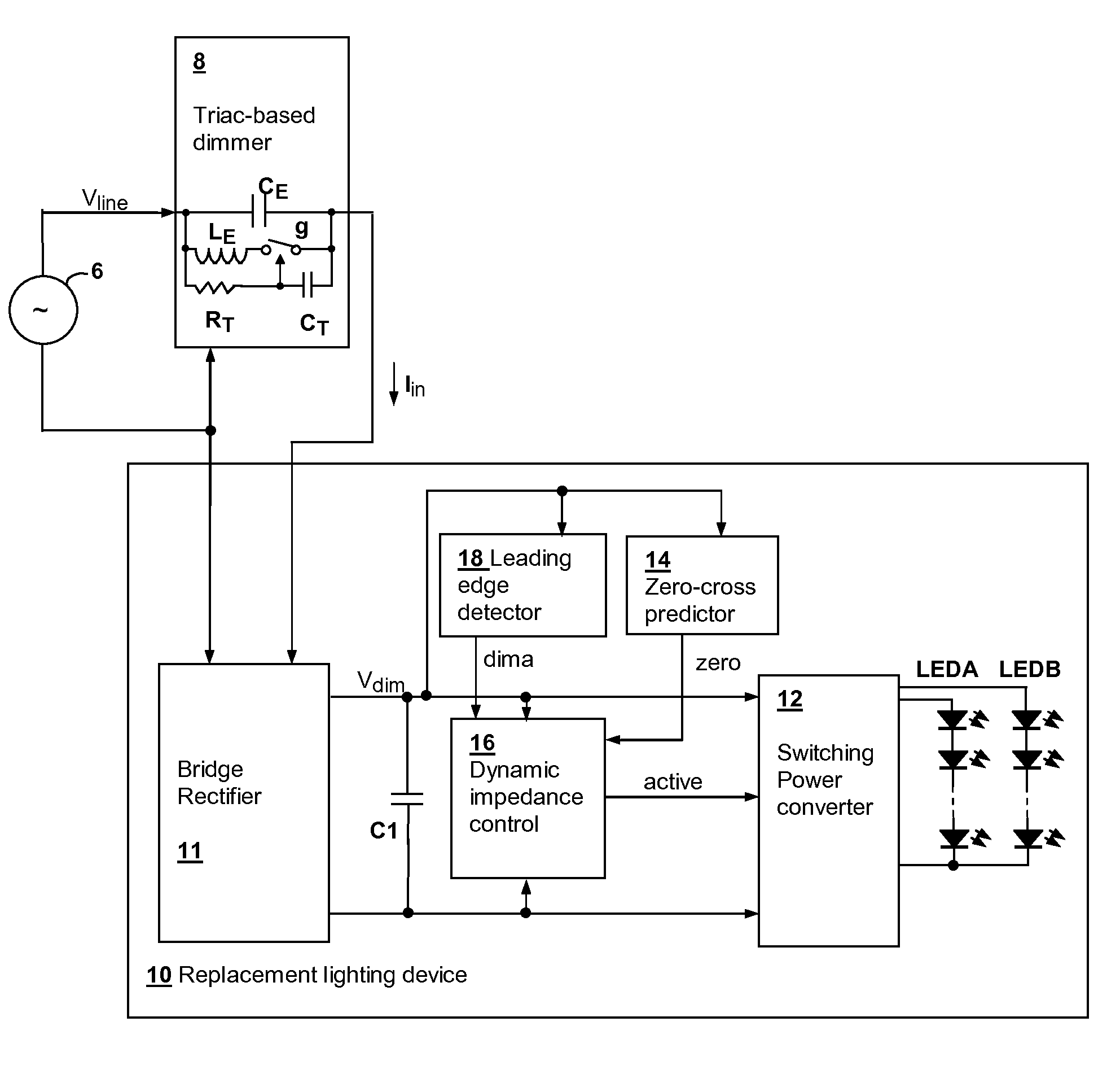
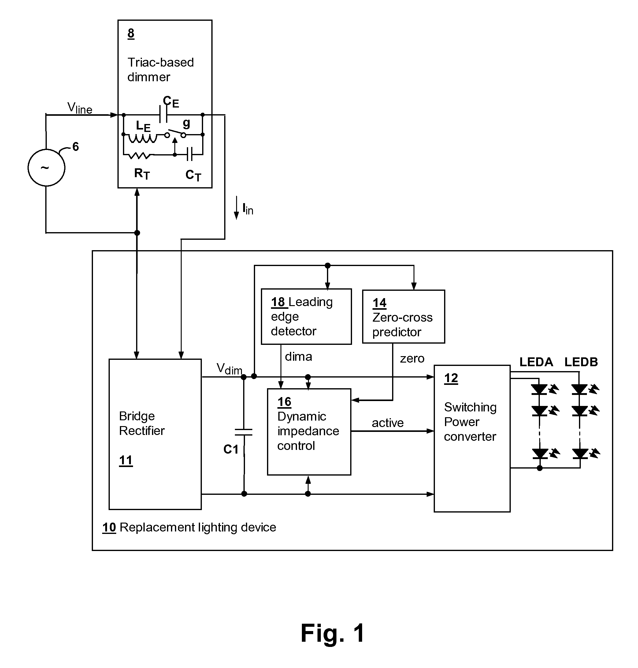
[0018]The present invention encompasses circuits and methods for powering and controlling lighting devices. In particular embodiments, strings of light-emitting diodes (LEDs) are packaged to replace incandescent lamps, and the energy supplied to the LED strings is varied in accordance with a dimming value determined from operation of a thyristor-controlled dimmer supplying the replacement lighting device, so that dimmed operation is achieved. The present invention achieves dimming operation efficiently without mis-firing of the thyristor in the dimmer by various features that are described in further detail below.

[0019]Referring now to FIG. 1, a lighting circuit in accordance with an embodiment of the invention is shown. An AC power line source 6 provides an AC line voltage Vline to a replacement lighting device 10 through a triac-based dimmer 8 that is, for example, designed for operation with incandescent bulbs having a power consumption of 40 W or greater. Replacement lighting de...


PUM


Abstract

A circuit for powering high-efficiency lighting devices from a thyristor-controlled dimmer predicts a zero-crossing time of the AC power line supplying the dimmer and causes a glue impedance to be imposed at the output of the dimmer starting at the time of the zero-crossing, so that the timer in the dimmer will operate properly to generate the turn-on event at the correct time. At turn-on, a lower level of impedance is presented to absorb the energy associated with the turn-on event. A higher level of impedance may be presented after the energy is absorbed until all of the energy needed for the cycle is transferred. Then, a high impedance state is maintained until the next zero-crossing time. The impedance control may be provided by non-uniform operation of a power converter that supplies the lighting devices, or by a combination of non-uniform power converter operation and dissipative loading.

Description

[0001]The present U.S. patent application claims priority under 35 U.S.C. §119(e) to U.S. Provisional Patent Applications Ser. No. 61 / 369,202 filed on Jul. 30, 2010, Ser. No. 61 / 410,269 filed on Nov. 4, 2010, and Ser. No. 61,437,355 filed on Jan. 28, 2011. The present U.S. patent application also claims priority under 35 U.S.C. §120 to U.S. patent application Ser. No. 12 / 858,164 entitled “DIMMER OUTPUT EMULATION”, filed on Aug. 17, 2010 and U.S. patent application Ser. No. 12 / 894,440, entitled “DIMMING MULTIPLE LIGHTING DEVICES BY ALTERNATING ENERGY TRANSFER FROM A MAGNETIC STORAGE ELEMENT”, filed on Sep. 30, 2010 each having at least one common inventor and assigned to the same Assignee. The disclosures of both of the above-referenced U.S. patent applications are incorporated herein by reference.BACKGROUND OF THE INVENTION[0002]1. Field of the Invention[0003]The present invention relates generally to lighting device power sources such as those included within dimmable light emittin...

Claims


Application Information

Patent Timeline
IPC IPC(8): H05B37/02H05B44/00
CPCH05B33/0815Y02B20/346H05B37/0263H05B33/0845H05B47/185H05B45/10Y02B20/30H05B45/385H05B45/3725H05B45/375
Inventor MELANSON, JOHN L.KING, ERIC
Owner SIGNIFY HLDG BV
Why Eureka
Try Eureka