Pulse filter and bridge driver using the same

a technology of pulse filter and bridge driver, applied in the field of pulse filter, can solve problems such as the blinking period, and achieve the effect of large noise margin, effective and robus

Inactive Publication Date: 2013-10-22
ALITEK TECH
View PDF4 Cites 7 Cited by
  • Summary
  • Abstract
  • Description
  • Claims
  • Application Information

AI Technical Summary

Benefits of technology

[0011]One objective of the present invention is to provide an effective and robust pulse filter having a large noise margin for a bridge driver.

Problems solved by technology

As a result, a certain period the capacitor takes to reach a stable state causes a glitch period.

Method used


Image

  • Pulse filter and bridge driver using the same
  • Pulse filter and bridge driver using the same
  • Pulse filter and bridge driver using the same

Examples


Embodiment Construction

[0034]The present invention will be described in more detail hereinafter with reference to the accompanying drawings that show the preferred embodiments of the invention.

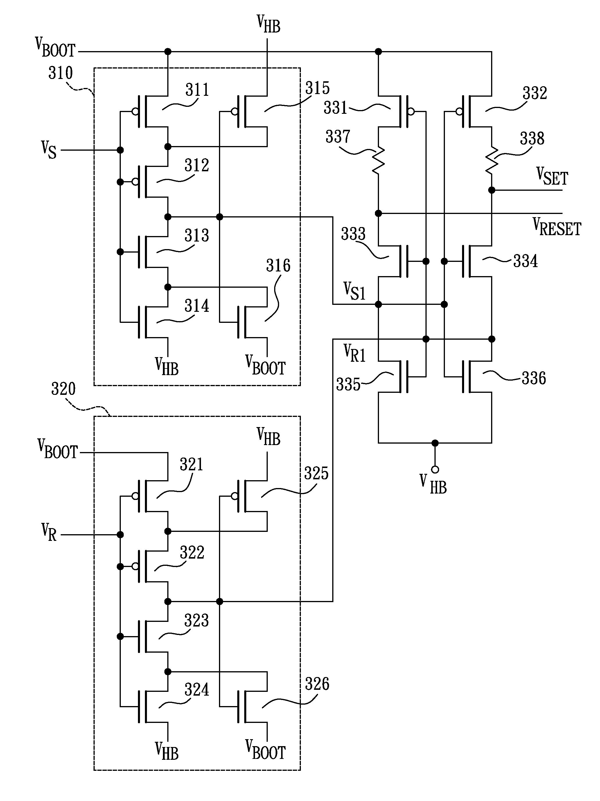
[0035]Please refer to FIG. 3, which illustrates a circuit diagram of a pulse filter according to a preferred embodiment of the present invention. As illustrated in FIG. 3, the pulse filter includes a first Schmitt trigger circuit 310, a second Schmitt trigger circuit 320, a first PMOS transistor 331, a second PMOS transistor 332, a first NMOS transistor 333, a second NMOS transistor 334, a third NMOS transistor 335, a fourth NMOS transistor 336, and resistors 337-338.

[0036]The first Schmitt trigger circuit 310, including a third PMOS transistor 311, a fourth PMOS transistor 312, a fifth NMOS transistor 313, a sixth NMOS transistor 314, a fifth PMOS transistor 315, and a seventh NMOS transistor 316, has an input coupled to a first set signal VS, and an output for providing a second set signal VS1 by performing a firs...


PUM


Abstract

A pulse filter and a bridge driver using the same, the pulse filter including: a first NMOS transistor, having a drain coupled to a first PMOS transistor for providing a reset signal, a gate coupled to a second reset signal, and a source coupled to a second set signal; a second NMOS transistor, having a drain coupled to a second PMOS transistor for providing a set signal, a gate coupled to the second set signal, and a source coupled to the second reset signal; a third NMOS transistor, having a drain coupled to the second set signal, a gate coupled to the second reset signal, and a source coupled to a second power line; and a fourth NMOS transistor, having a drain coupled to the second reset signal, a gate coupled to the second set signal, and a source coupled to the second power line.

Description

BACKGROUND OF THE INVENTION[0001]1. Field of the Invention[0002]The present invention relates to a pulse filter, and more particularly to a pulse filter in a half-bridge or full-bridge driver.[0003]2. Description of the Related Art[0004]To describe the related art of the present invention, the relation between a pulse filter and a half-bridge or full-bridge driver shall be introduced first. Please refer to FIG. 1, which shows the architecture of a typical half-bridge driver 100. As shown in FIG. 1, the typical half-bridge driver 100 at least includes a pulse generator 101, a level shifter 102, a pulse filter 103, and a latch 104.[0005]The pulse generator 101 is used for generating a first clock signal CLK and a second clock signal CLKB, wherein the first clock signal CLK is interleaved with the second clock signal CLKB. The level shifter 102 is used to up shift the first clock signal CLK and the second clock signal CLKB from low side to provide counterpart signals for the pulse filt...

Claims


Application Information

Patent Timeline
Patent Type & Authority Patents(United States)
IPC IPC(8): H03K5/00
CPCH03K5/1252
Inventor WANG, YEN-PING
Owner ALITEK TECH
Why Eureka
Try Eureka