Optimized movable ir filter in cameras

a technology of movable ir filters and cameras, applied in the field of cameras, can solve the problems of increasing the exposure time, challenging the most image capturing devices, and taking longer to capture each image, and achieve the effect of simple and intuitive manner

Active Publication Date: 2012-02-02
LOGITECH EURO SA
View PDF11 Cites 92 Cited by
  • Summary
  • Abstract
  • Description
  • Claims
  • Application Information

AI Technical Summary

Benefits of technology

[0011]Embodiments of the present invention include a camera that functions well not only in well-lit environments, but also in very low visible light or no visible light environments, and where the image remains in focus regardless of whether visible light is used or non-visible (e.g., IR) light is used to capture the image. Further, a camera in accordance with an embodiment of the present invention can function in a gamut of visible light environments, and can be switched from a sufficient visible light mode to an infra-red light mode in a simple and intuitive manner. Moreover, an algorithm in accordance with an embodiment of the present invention determines when sufficient visible light is present and when it is not.
[0013]In accordance with an embodiment of the present invention, a camera has two modes: a visible light imaging mode (also referred to as “day-mode” or “sufficient visible light mode”) and am IR imaging mode (also referred to as “night-mode” or “non-visible mode” or “insufficient visible light mode”). In one embodiment, in the visible light imaging mode, the IR filter is in line with the lens assembly, and / or is part of the lens stack in front of the sensor. In the IR imaging mode, the IR filter is mechanically removed from the lens stack, and IR light is allowed to pass to the sensor. In one embodiment, in the IR imaging mode, IR lighting is provided by an array of IR LEDs on the camera to illuminate the scene. These two modes allow the camera to function both when sufficient visible light is present, and when it is not, but other non-visible light (e.g., IR light) is (or can be made) available.
[0014]In one embodiment, the IR filter is rotatably coupled to a frame, so that it can be rotated in and out of a position in front of the sensor. Such a rotatable mechanism allows the IR filter to be removable, while still taking up very little space and thus allowing for a compact form factor of the camera. Also, in one embodiment, an aperture in the camera is such that it accommodates an f#2 lens and a ⅓″ imager.

Problems solved by technology

One of the challenges for imaging capturing devices is to capture acceptable quality images in a variety of lighting conditions.
Most image capturing devices are challenged by very low visible light or no visible light conditions.
There are several problems with such cameras.
For one thing, increase in the exposure time implies that it takes longer to capture each image.
This can be unacceptable or undesirable in certain situations, such as in a security / surveillance camera where a delay in capturing an image can result in missed information.
This can also be undesirable if a video stream is being captured, since this results in a lower frame-rate.
Further, this solution alone still requires a certain amount of visible light to be present, and thus will not function in really low visible light or no visible light environments.
Other conventional cameras may use other solutions which also suffer from several problems, and which again require at least a certain amount of visible light, and will not work in extremely low or no visible light environments.
It is therefore particularly difficult to produce good video in night conditions.
Further, it is not desirable to use a visible light source on a surveillance camera—this may alert intruders, disturb neighbors, etc.
Thus such cameras have very poor resolution and thus produce poor quality images in many lighting environments, including when visible light is present.
IR light poses problems in normal (visible) lighting conditions.
This is particularly problematic because in natural light, plenty of IR light is included with all the visible light.
However, when this IR blocking filter is in place, low or no visible light conditions are problematic, as discussed above.

Method used


Image

  • Optimized movable ir filter in cameras
  • Optimized movable ir filter in cameras
  • Optimized movable ir filter in cameras

Examples


Embodiment Construction

[0033]The figures (or drawings) depict embodiments of the present invention for purposes of illustration only. It is noted that similar or like reference numbers in the figures may indicate similar or like functionality. One of skill in the art will readily recognize from the following discussion that alternative embodiments of the structures and methods disclosed herein may be employed without departing from the principles of the invention(s) herein.

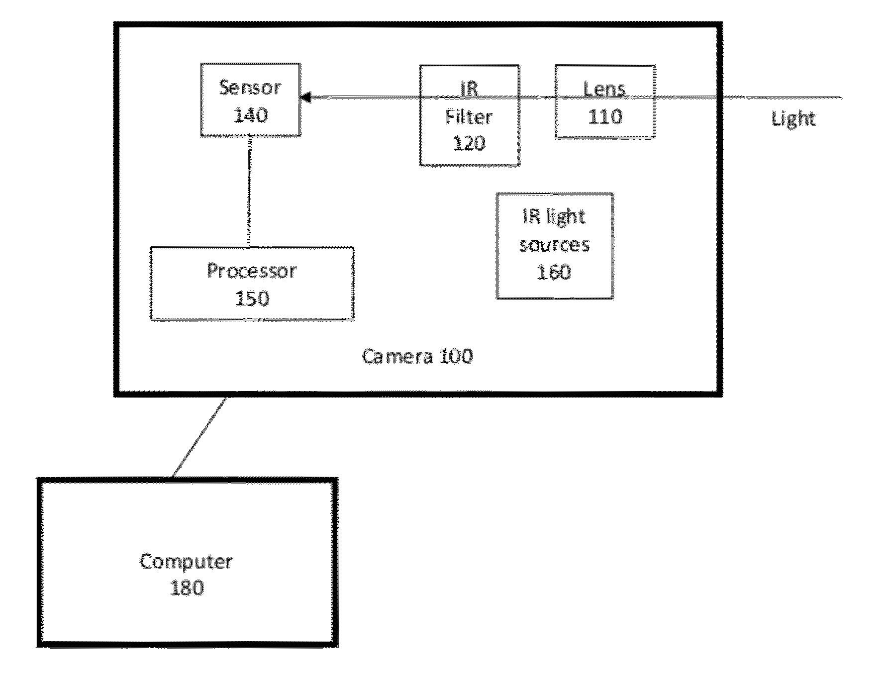
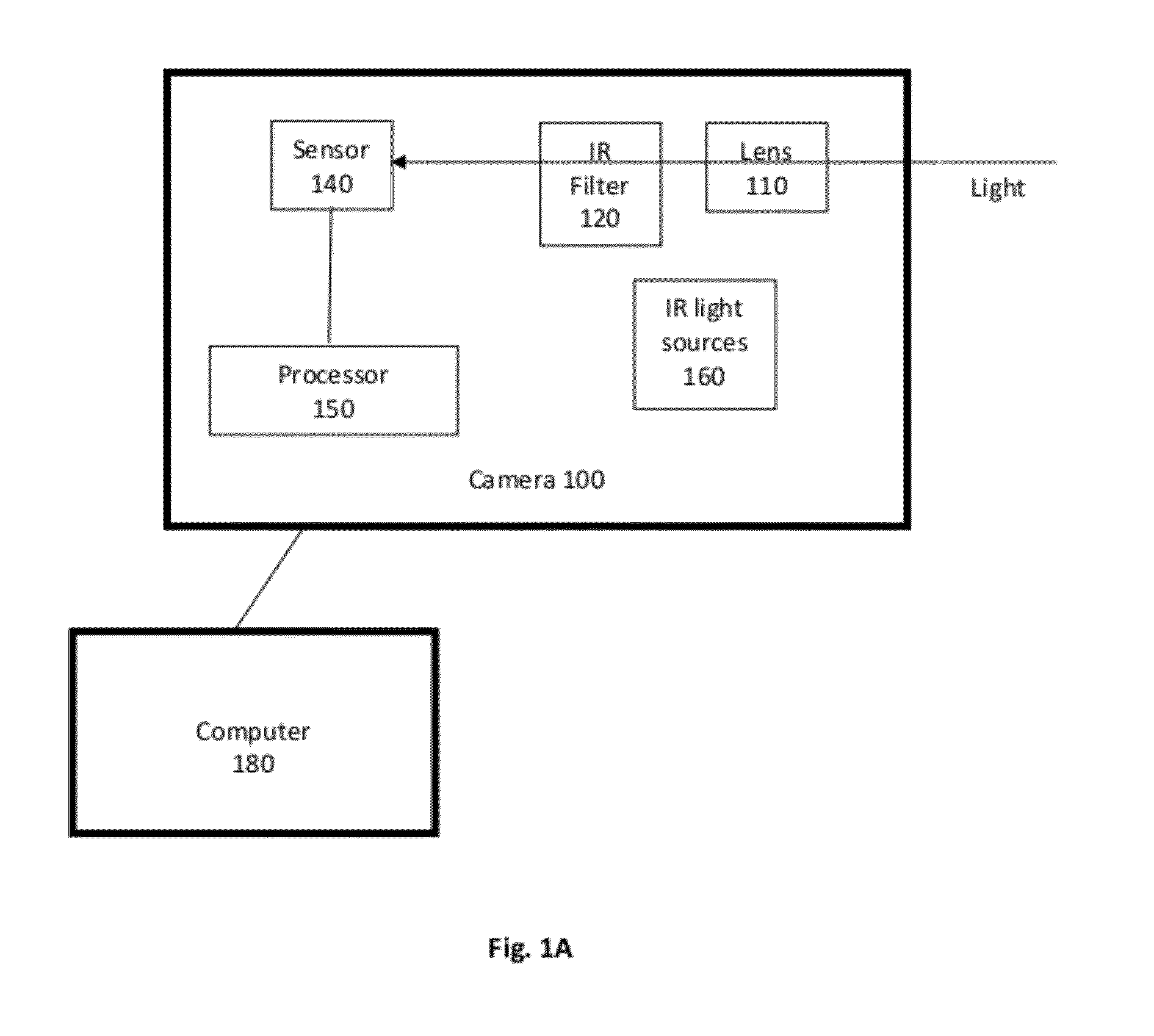
[0034]It is to be noted that the term “camera” refers here to any kind of image capture device. Such a device may capture video alone, still images alone, or both. Additionally, such a camera may also capture audio. Further, such a camera can be a stand-alone device, or be integrated into another device such as a smart phone, a cell phone, a personal digital assistant (PDA), a laptop, a tablet, a set-top box, a remote control, and so on. Further, such a camera may include all the required processors within the same physical device, or m...


PUM


Abstract

Embodiments of the present invention include a camera having two modes: a visible light imaging mode (day-mode) and an IR imaging mode (night-mode). In the visible light imaging mode, an IR filter is in line with the lens assembly. In the IR imaging mode, the IR filter is mechanically removed, and IR light is allowed to pass to the sensor. In one embodiment, in the IR imaging mode, IR lighting is provided by an IR LEDs on the camera to illuminate the scene. In one embodiment, the various components are chosen, balanced and optimized so that images captured using visible light and images captured using non-visible light are both in focus. In one embodiment, an algorithm determines when there sufficient visible light is present and when it is not, and thus determines when to switch the camera from one mode to another.

Description

BACKGROUND[0001]1. Field of the Invention[0002]The present invention relates generally to cameras, and more particularly to cameras for producing acceptable quality video data in varying lighting conditions.[0003]2. Description of the Related Arts[0004]One of the challenges for imaging capturing devices is to capture acceptable quality images in a variety of lighting conditions. Most image capturing devices are challenged by very low visible light or no visible light conditions.[0005]Some conventional cameras have a “night mode” which can be used for capturing images in low light conditions. However, some of these conventional cameras simply increase the exposure time in the “night mode”, so as to gather sufficient light in low light conditions. There are several problems with such cameras. For one thing, increase in the exposure time implies that it takes longer to capture each image. This can be unacceptable or undesirable in certain situations, such as in a security / surveillance ...

Claims


Application Information

Patent Timeline
Patent Type & Authority Applications(United States)
IPC IPC(8): H04N5/33H04N7/18
CPCG03B11/00H04N5/23245H04N5/2254H04N23/55H04N23/667
Inventor BUNKER, PHILIP ALANNELSON, MARKLANCASTER, JEFFREY B.WEBB, TODDHSU, TING CHIATAI, EVA
Owner LOGITECH EURO SA
Why Eureka
Try Eureka