Wireless communication system, wireless communication device, and wireless communication method

a wireless communication and wireless communication technology, applied in the field of wireless communication systems, wireless communication devices, wireless communication methods, etc., can solve problems such as frequency use efficiency

Active Publication Date: 2012-02-09
SHARP KK
View PDF11 Cites 130 Cited by
  • Summary
  • Abstract
  • Description
  • Claims
  • Application Information

AI Technical Summary

Benefits of technology

[0026]According to the present invention, in the wireless communication system that can perform cooperative communicat

Problems solved by technology

However, there has been a problem re

Method used


Image

  • Wireless communication system, wireless communication device, and wireless communication method
  • Wireless communication system, wireless communication device, and wireless communication method
  • Wireless communication system, wireless communication device, and wireless communication method

Examples


first embodiment

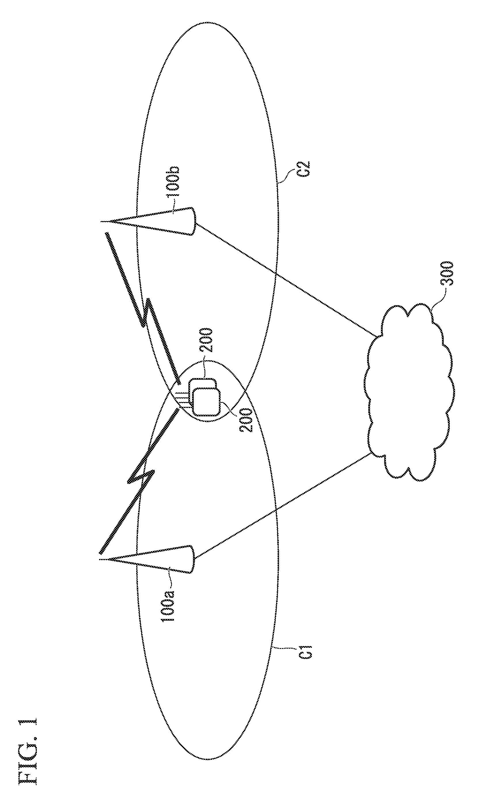
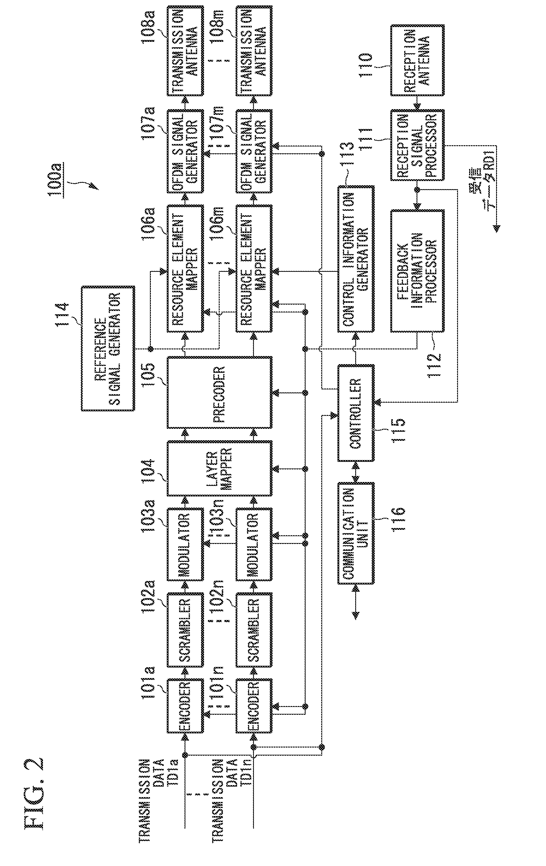
[0060]Hereinafter, a first embodiment of the present invention is explained with reference to the drawings. FIG. 1 is a schematic diagram illustrating a configuration of a wireless communication system according to the first embodiment. A mobile communication system, which is the wireless communication system of the first embodiment, includes: base station devices 100a and 100b (also referred to as first communication devices, cells, transmission points, or transmission antenna groups); multiple mobile terminal devices 200 (also referred to as second communication devices or reception terminals) each of which communicates with the base station devices 100a and 100b; a network 300 connecting the base station devices 100a and 100b. In the case of FIG. 1, the mobile terminal device 200 is present in a region where a cell C1 that is a communication area served by the base station device 100a overlaps a cell C2 that is a communication area served by the base station device 100b. The base...

second embodiment

[0155]Hereinafter, a second embodiment of the present invention is explained. A wireless communication system according to the present invention includes similar base station devices 100a and 100b and a similar mobile terminal device 200 to those included in the communication system of the first embodiment. Among the resource element mappers 106a to 106m of the base station device 100a, a mapping method for the resource element mappers associated with the antenna ports 5 to 8 differ. Hereinafter, the portions differing from those of the first embodiment are mainly explained.

[0156]A case, in which the base station devices 100a and 100b add more antenna ports to antenna ports P1a to P4a and P1b to P4b which support the mobile terminal device 200 that communicates with only the base station devices 100a and 100b, as shown in FIG. 9, is explained in the second embodiment. Added antenna ports P5a to P8a and P5b to P8b support both the case where the mobile terminal device 200 communicate...

third embodiment

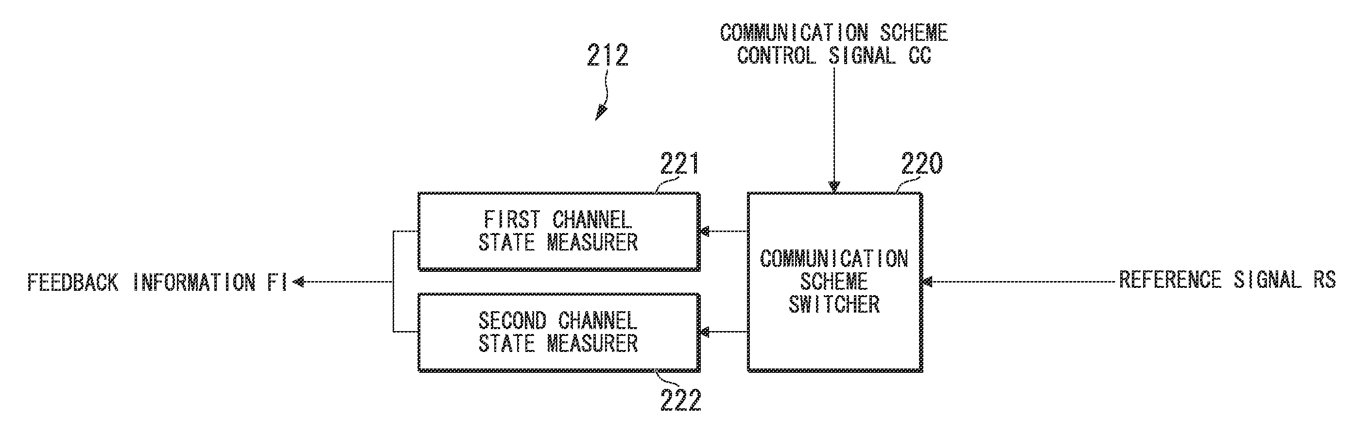
[0170]Hereinafter, a third embodiment of the present invention is explained. A mobile communication system of the third embodiment includes similar base station devices 100a and 100b and a similar mobile terminal device 200a to those included in the mobile communication system of the first embodiment. Only a feedback information generator 212a of the mobile terminal device 200a differs from that of the mobile terminal device 200 of the first embodiment. Hereinafter, the different portions from those of the first embodiment are mainly explained.

[0171]FIG. 14 is a schematic block diagram illustrating a configuration of a mobile terminal device 200a according to the third embodiment. The mobile terminal device 200a includes: reception antennas 201a to 201l; OFDM signal demodulators 202a to 2021; resource element demappers 203a to 203l; a filter unit 204; a deprecoder 205; a layer demapper 206; demodulators 207a to 207n; descramblers 208a to 208n; decoders 209a to 209n; a channel estima...


PUM


Abstract

A wireless communication system includes a first channel state measurer and a second channel state measurer. When a second communication device measures a state of a channel between the second communication device and a first communication device using reference signals transmitted from the first communication device, the first channel measurer is configured to measure a state of the channel including an interference due to a signal transmitted from another first communication device. When measuring the state of the channel between the second communication device and the first communication device using the reference signals transmitted from the first communication device, the second channel state measurer measures the state of the channel while suppressing the interference due to the signal transmitted from the another first communication device. Accordingly, the wireless communication system can generate adequate feedback information both when cooperative communication is performed and when cooperative communication is not performed.

Description

TECHNICAL FIELD[0001]The present invention relates to a wireless communication system, a wireless communication device, and a wireless communication method.[0002]Priority is claimed on Japanese Patent Application No. 2009-106251, filed Apr. 24, 2009, the content of which is incorporated herein by reference.BACKGROUND ART[0003]A wireless communication system, such as LTE ((third generation) Long Term Evolution), LTE-Advanced (Advanced LTE), and WiMAX (Worldwide Interoperability for Microwave Access), employs a cellular configuration in which multiple areas covered by a base station (a transmission station, a transmission device, or eNodeB) are arranged in a cellular manner, thereby enabling an increase in wider communication areas. Additionally, different frequencies are used between neighboring cells (sectors) so that a mobile terminal (a reception station, a mobile station, a mobile terminal device 200, or UE (User Equipment)) can perform communication without being subjected to in...

Claims


Application Information

Patent Timeline
IPC IPC(8): H04B15/00H04L12/26
CPCH04B7/026H04B17/345H04B7/0678H04B7/068H04B7/0689H04B7/0854H04J11/0053H04L1/0026H04L5/0016H04L5/0023H04L5/0035H04L5/0048H04L5/0053H04L5/0073H04L25/0234H04L25/03343H04L2001/0092H04L2025/03426H04L2025/03808H04W72/082H04B7/0671H04W72/541
Inventor SHIMEZAWA, KAZUYUKINOGAMI, TOSHIZOYAMADA, SHOHEI
Owner SHARP KK
Why Eureka
Try Eureka