Supercharge Your Innovation With Domain-Expert AI Agents!

Hydrodynamic gas film bearing cooling flow control system

a technology control systems, which is applied in the direction of bearing cooling, bearings, shafts and bearings, etc., can solve the problems of increasing the overall engine fuel consumption, unregulated cooling gas systems of hydrodynamic gas film bearings, and inability to control the flow of cooling for varying conditions

Inactive Publication Date: 2012-02-09
HONEYWELL INT INC
View PDF5 Cites 1 Cited by
  • Summary
  • Abstract
  • Description
  • Claims
  • Application Information

AI Technical Summary

Benefits of technology

[0005]In one embodiment, and by way of example only, a hydrodynamic gas film bearing cooling gas control system includes a hydrodynamic gas film bearing, a supply conduit, and a flow control device. The supply conduit is in fluid communication with the hydrodynamic gas film bearing, is coupled to receive a flow of cooling gas from a cooling gas supply source, and is configured to supply the flow of cooling gas to the hydrodynamic gas film bearing. T

Problems solved by technology

A typical cooling gas system for hydrodynamic gas film bearings is unregulated, meaning that it does not controllably adjust the flow of cooling for varying conditions.
Hence, oversupplying a hydrodynamic gas film bearing with cooling gas may increase overall engine fuel consumption.

Method used


Image

  • Hydrodynamic gas film bearing cooling flow control system
  • Hydrodynamic gas film bearing cooling flow control system
  • Hydrodynamic gas film bearing cooling flow control system

Examples


Embodiment Construction

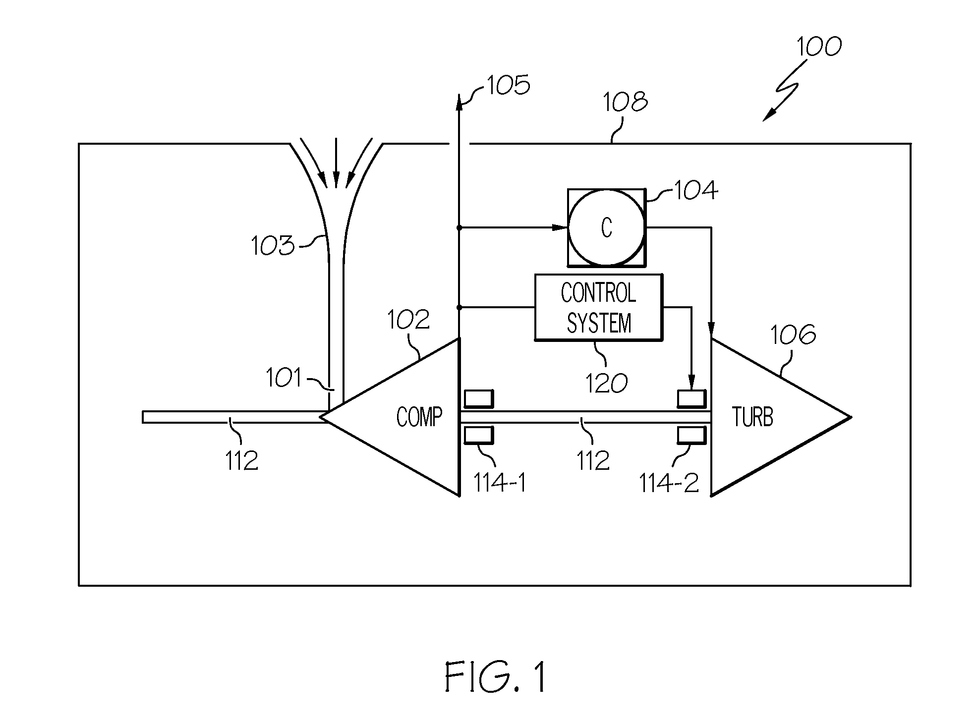
[0014]The following detailed description is merely exemplary in nature and is not intended to limit the invention or the application and uses of the invention. As used herein, the word “exemplary” means “serving as an example, instance, or illustration.” Thus, any embodiment described herein as “exemplary” is not necessarily to be construed as preferred or advantageous over other embodiments. All of the embodiments described herein are exemplary embodiments provided to enable persons skilled in the art to make or use the invention and not to limit the scope of the invention which is defined by the claims. Furthermore, there is no intention to be bound by any expressed or implied theory presented in the preceding technical field, background, brief summary, or the following detailed description. Thus, although the description is explicitly directed toward an embodiment that is implemented in a gas turbine engine, it should be appreciated that it can be implemented in various other typ...


PUM


Abstract

A hydrodynamic gas film bearing cooling gas control system includes a hydrodynamic gas film bearing, a supply conduit, and a flow control device. The supply conduit is in fluid communication with the hydrodynamic gas film bearing, is coupled to receive a flow of cooling gas from a cooling gas supply source, and is configured to supply the flow of cooling gas to the hydrodynamic gas film bearing. The flow control device is coupled to the supply conduit and is responsive to a physical characteristic of the cooling gas or ambient environment to move between at least two positions to thereby vary the flow of cooling gas, through the supply conduit, to the hydrodynamic gas film bearing.

Description

TECHNICAL FIELD[0001]The present invention generally relates to hydrodynamic gas film bearings, and more particularly relates to a system for adaptively controlling cooling flow to hydrodynamic gas film bearings.BACKGROUND[0002]Hydrodynamic gas film bearings may be used in various high-speed rotating machines. A hydrodynamic gas film bearing runs on a film of gas, which allows it to operate without oil. During operation, a hydrodynamic gas film bearing generates heat. To remove the generated heat, a flow of cooling gas is supplied to the hydrodynamic gas film bearing. The cooling gas flows into the hydrodynamic gas film bearing, absorbs the heat, and exits the hydrodynamic gas film bearing carrying away the heat. As may be appreciated, the cooling gas supply system is preferably designed to provide sufficient cooling gas to maintain metal temperatures within acceptable limits.[0003]Cooling gas requirements for hydrodynamic gas film bearings can vary significantly with bearing load, ...

Claims


Application Information

Patent Timeline
IPC IPC(8): F16C32/06
CPCF16C37/002F16C17/026
Inventor GIBSON, NATHANTAKEUCHI, DONMEACHAM, WALTER LEEKNORR, JAMES
Owner HONEYWELL INT INC
Features
  • R&D
  • Intellectual Property
  • Life Sciences
  • Materials
  • Tech Scout
  • Unparalleled Data Quality
  • Higher Quality Content
  • 60% Fewer Hallucinations
Learn More