
HVAC Air Inlet with Blend Mode and Fresh-Restricted Mode

a technology of air inlet and filter mode, which is applied in the direction of vehicle heating/cooling devices, vehicle components, transportation and packaging, etc., can solve the problems of increasing the cost of the second door and its actuator, the inability to meet the performance criteria of heater and defrosting, and the inability to ram the air

Active Publication Date: 2012-02-09
FORD GLOBAL TECH LLC
View PDF13 Cites 12 Cited by
  • Summary
  • Abstract
  • Description
  • Claims
  • Application Information

AI Technical Summary

Benefits of technology

The invention is an air inlet system for a car's heating, ventilation, and air conditioning system. It has a housing with two cylindrical segments, one of which has a fresh air aperture and one of which has a recirculation aperture. There is also an outlet body with an exit aperture. A pivoting door element is mounted inside the housing and can be positioned to block either the fresh air aperture or the recirculation aperture. This allows the system to control the air flow and direct it to either the fresh air or recirculation system. The technical effect of this invention is to provide a more efficient and precise control over the air flow in a car's HVAC system.

Problems solved by technology

In modern vehicles with smaller, more efficient engines designed to meet increased fuel economy requirements, it has become more difficult to meet heater and defrost performance criteria.
A significant disadvantage of conventional single door blend systems is that as the vehicle speed increases, a ram air effect can force unconditioned air from the fresh air passage into the cabin via the recirculated air passage.
Disadvantages include the cost of the second door and its actuator as well as increased noise since the incoming fresh air passes through two openings.
Added components can also result in moving parts that generate additional squeaks, rattles, and scrapes.

Method used


Image

  • HVAC Air Inlet with Blend Mode and Fresh-Restricted Mode
  • HVAC Air Inlet with Blend Mode and Fresh-Restricted Mode
  • HVAC Air Inlet with Blend Mode and Fresh-Restricted Mode

Examples


Embodiment Construction

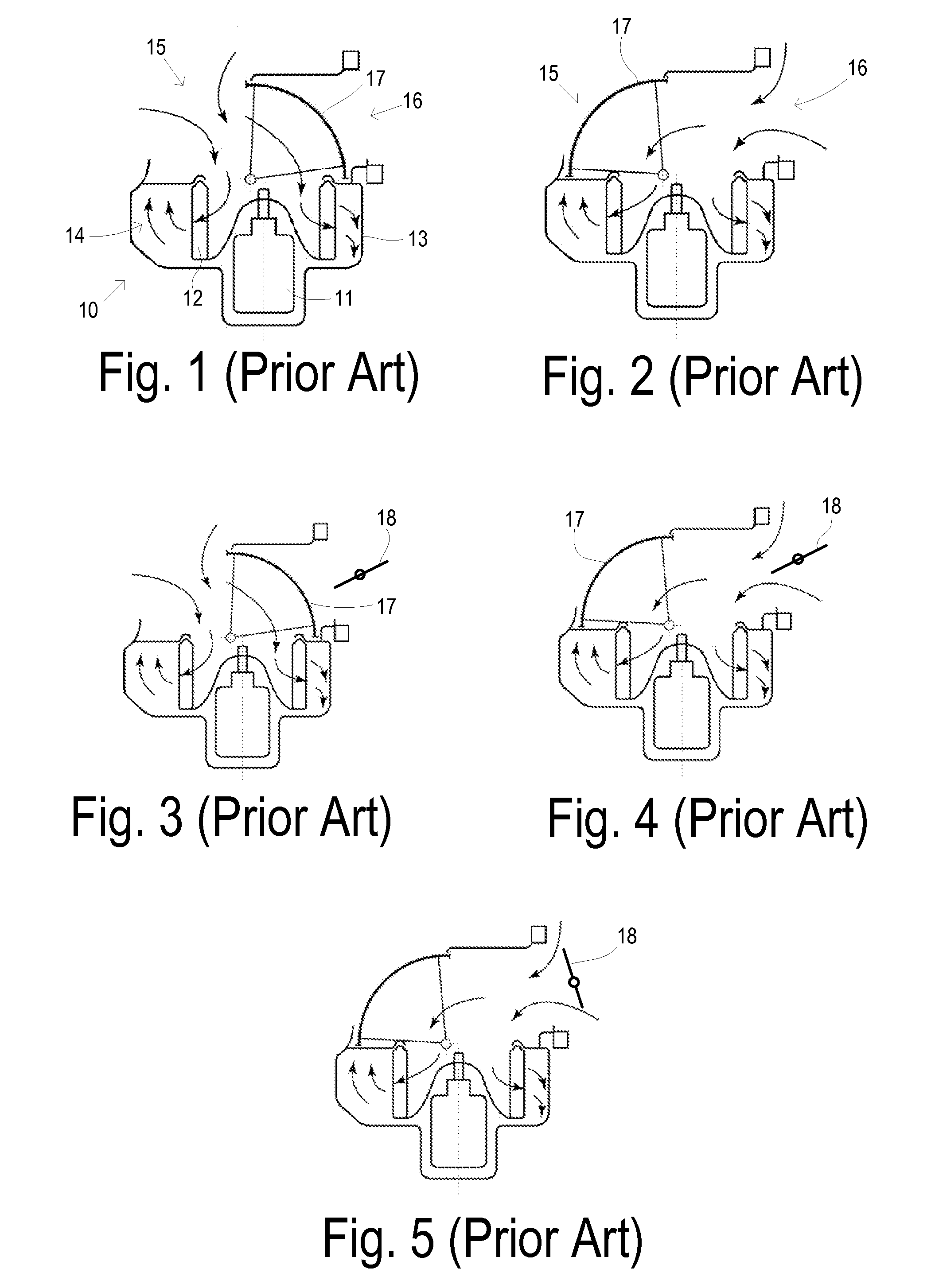
[0023]One conventional type of air inlet mechanism using what is known as a football-style door as shown in FIGS. 1 and 2. A blower system 10 has an electric motor 11 driving a set of blades 12 which are all contained in a housing 13. Inlet air is blown by set of blades 12 into an outlet 14 from blower system 10. Housing 13 includes a recirculation inlet 15 and a fresh air inlet 16 which may be controllably blocked by football door 17 which is shown in the full recirculation mode in FIG. 1. By pivoting door 17 fully counterclockwise as shown in FIG. 2, a full fresh mode is obtained. Football door 17 may also be pivoted to an intermediate position where it blocks complementary portions of the recirculation inlet and fresh air inlet to provide a blend mode.

[0024]In order to provide a fresh restricted mode in connection with the football-style door, a butterfly door 18 is provided as shown in FIGS. 3-5. With butterfly door 18 in its open position, football door 17 may be positioned to ...


PUM


Abstract

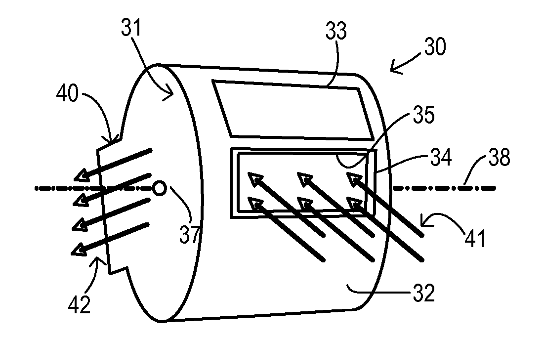
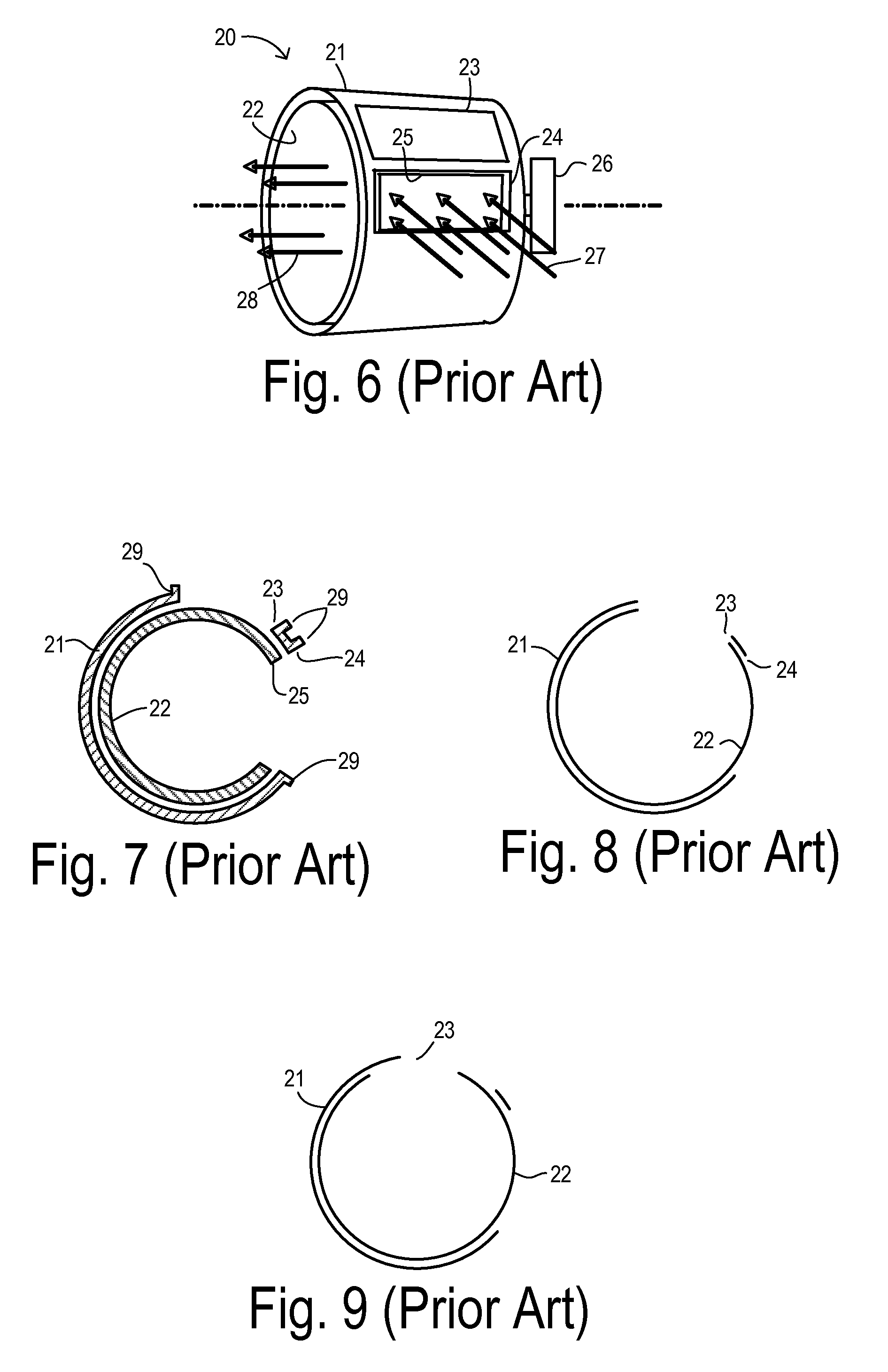
An air inlet system for an automotive HVAC system has a housing comprising a first cylindrical segment enclosing an interior space and having a first radial surface with a first angular divergence. The first radial surface has a fresh air aperture and a recirculation aperture for radially receiving fresh air and recirculated air, respectively. The housing further comprises an outlet body with an exit aperture. A pivoting door element is mounted in the interior space and shaped as a second cylindrical segment with a second radial surface with a second angular divergence which is less than the first angular divergence. The door element has a pivot axis that allows the second radial surface to slide along the first radial surface. The door element pivots to selectably align the opening with the fresh air aperture or the recirculation aperture in order to 1) block the fresh air aperture without blocking the recirculation aperture, 2) simultaneously block portions of the fresh air aperture and the recirculation aperture, 3) block the recirculation aperture without blocking any of the fresh air aperture, or 4) block the recirculation aperture while blocking only a portion of the fresh air aperture.

Description

CROSS REFERENCE TO RELATED APPLICATIONS[0001]Not Applicable.STATEMENT REGARDING FEDERALLY SPONSORED RESEARCH[0002]Not Applicable.BACKGROUND OF THE INVENTION[0003]The present invention relates in general to automotive heating, ventilating, and air conditioning (HVAC) systems, and, more specifically, to an air inlet system for selectably supplying a blower with fresh air, recirculated air, or a blend of fresh and recirculated air.[0004]An air inlet mechanism of a typical HVAC system is used to control the blend of inflowing air from two air source passages into the blower for passing the air across one or more heat exchangers before distributing it to the passenger compartment. Fresh outside air is available from one air source passage and recirculated cabin air is available from the other. The inlet mechanism settings determine the mix of air coming from each source. Each setting is referred to as a mode. The modes may include 1) fully recirculated, 2) fresh and recirculated combined...

Claims


Application Information

Patent Timeline
Patent Type & Authority Applications(United States)
IPC IPC(8): B60H1/34
CPCB60H1/00685B60H2001/00721B60H2001/00085
Inventor MEEHAN, TRENTON S.JAIRAZBHOY, VIVEK A.KAHRS, STEVE M.
Owner FORD GLOBAL TECH LLC
Learn More