Automotive HVAC system and method of operating same utilizing trapped coolant

a technology of hvac system and coolant, which is applied in the direction of domestic cooling apparatus, lighting and heating apparatus, heating types, etc., can solve the problems of difficult to keep the passenger compartment cool, and achieve the effect of reducing emissions, reducing the temperature of the hvac duct, and saving fuel

Inactive Publication Date: 2006-06-20
GM GLOBAL TECH OPERATIONS LLC
View PDF5 Cites 10 Cited by
  • Summary
  • Abstract
  • Description
  • Claims
  • Application Information

AI Technical Summary

Benefits of technology

[0006]An advantage of the present invention is that the cooled coolant in the heater core is utilized when the engine is not running in hybrid vehicles to continue to provide cool air to the passenger compartment, which results in extended engine-off periods, leading to additional fuel savings and emissions reduction.
[0007]The method and HVAC system may also be utilized with conventional internal combustion engine vehicles whereby the flow of coolant through the heater core may be blocked and the coolant cooled, with the trapped coolant in the heater core available to provide precooling for the HVAC system at a later time. Alternatively, the trapped coolant can be used for mild tempering or mixing to avoid excessive cooling and then reheating of the air in the HVAC duct. In the cooling mode, preventing hot coolant flowing through the heater core also advantageously reduces the temperature in the HVAC duct as a result of preventing the higher temperature heater core from warming up air flowing near it.

Problems solved by technology

Hybrid vehicles, which utilize a battery and an intermittently operated internal combustion engine for vehicle propulsion, have difficulty keeping the passenger compartment cool when the engine is off.

Method used


Image

  • Automotive HVAC system and method of operating same utilizing trapped coolant
  • Automotive HVAC system and method of operating same utilizing trapped coolant
  • Automotive HVAC system and method of operating same utilizing trapped coolant

Examples


Embodiment Construction

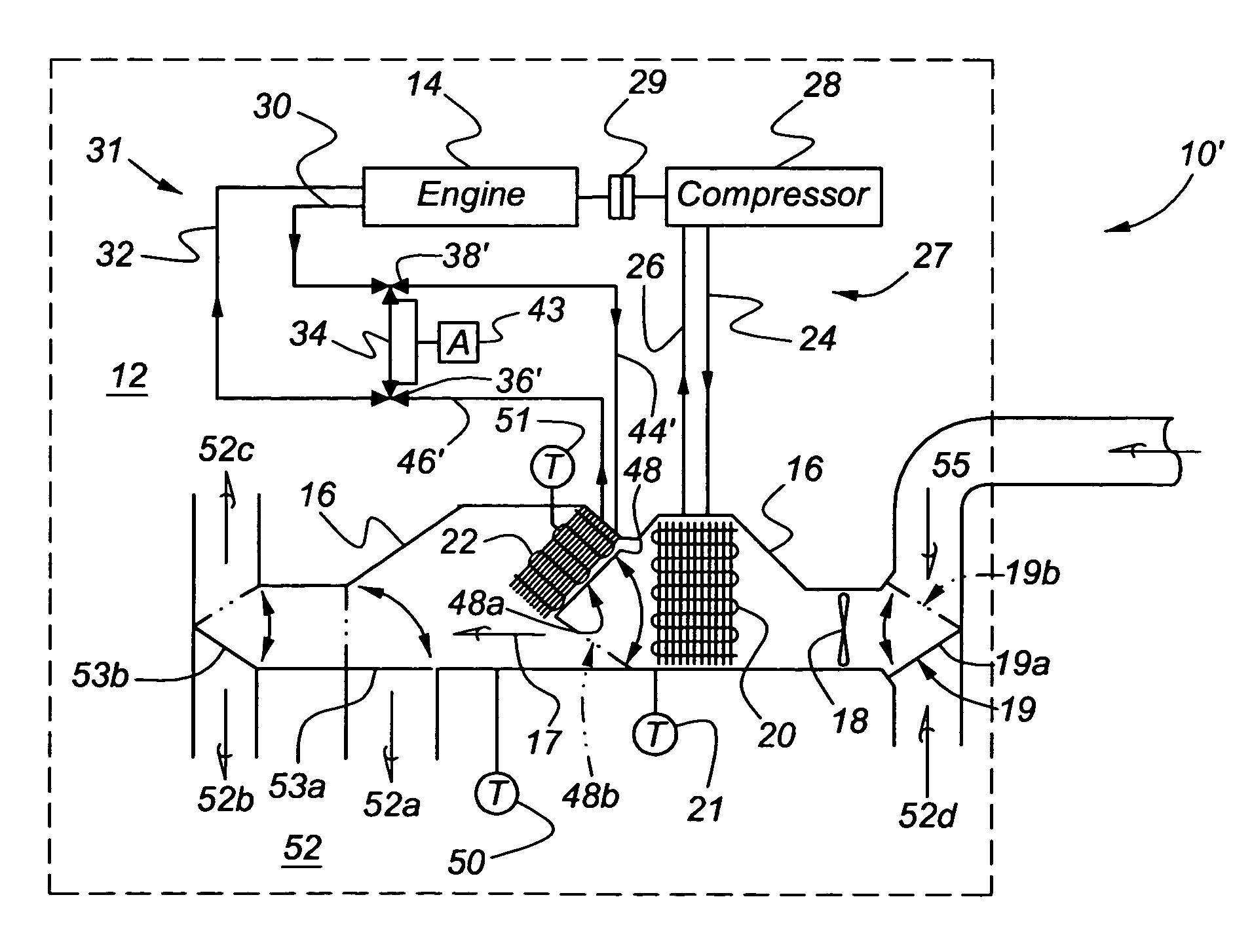
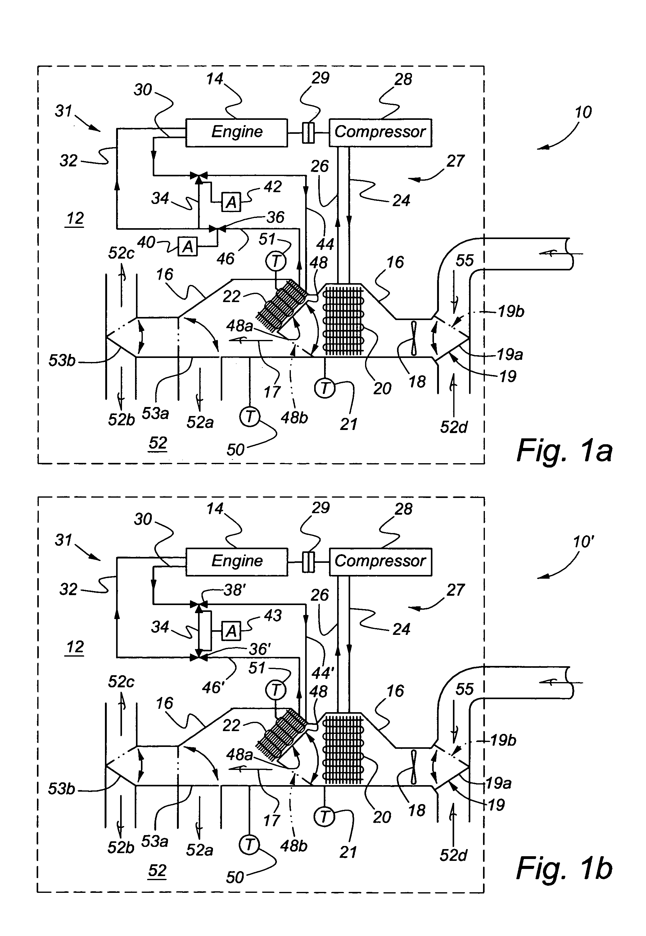
[0013]Referring now to FIGS. 1a and 1b, a HVAC system in accordance with the present invention is indicated generally at 10 in FIG. 1a and at 10′ in FIG. 1b. The HVAC system 10 and 10′ is disposed in a vehicle, indicated generally at 12. The vehicle 12 may be a hybrid vehicle having an internal combustion engine 14 operating in conjunction with a battery (not shown) or a conventional vehicle having the internal combustion engine 14 only. The HVAC system includes a HVAC air duct 16 and a blower 18 adapted to direct a flow of air in a direction indicated by an arrow 17 through the HVAC duct 16. Preferably, the blower 18 is powered by an electric motor or the like. An evaporator 20 is located within the HVAC duct 16 downstream of the blower 18. A heater core 22 is located within the HVAC duct 16 downstream of the evaporator 20. The evaporator 20 includes a refrigerant inlet 24 from and a refrigerant outlet 26 to a refrigerant circuit, indicated generally at 27, including a refrigerant ...


PUM


Abstract

The present invention concerns a method for cooling a passenger compartment in a hybrid vehicle that operates an engine intermittently during vehicle operation. The hybrid vehicle includes an HVAC system having an HVAC duct, a blower for directing a flow of air through the HVAC duct, an evaporator located within the HVAC duct, and a heater core. The heater core has a coolant inlet outlet and is located downstream of the evaporator in the HVAC duct. The method includes the steps of cooling a refrigerant; inducing a flow of the cooled refrigerant through the evaporator; blocking a flow of coolant through the coolant inlet and outlet to trap coolant in the heater core; activating the blower to move air through the evaporator and heater core; turning off the vehicle engine; measuring a duct outlet temperature; and starting the engine when the measured duct outlet temperature is above a predetermined temperature.

Description

BACKGROUND OF THE INVENTION[0001]The present invention relates generally to automotive HVAC systems and methods of operating such HVAC systems.[0002]Automotive HVAC systems are well known and are utilized for heating and cooling the passenger compartments of vehicles. Hybrid vehicles, which utilize a battery and an intermittently operated internal combustion engine for vehicle propulsion, have difficulty keeping the passenger compartment cool when the engine is off. When the engine is off, the HVAC compressor, typically run by a clutch connected to the engine, is also off and the temperature in the passenger compartment can rise quickly. The hybrid vehicle is most efficient when the engine is not running and, therefore, any extended increment of time that the engine is off increases fuel savings and reduces emissions.[0003]It is desirable, therefore, to provide an HVAC system that allows for extended engine off time in hybrid vehicles while keeping the passenger compartment of the v...

Claims


Application Information

Patent Timeline
Patent Type & Authority Patents(United States)
IPC IPC(8): F25B29/00B60H1/00B60H1/32B60H3/00F28D7/10
CPCB60H1/005B60H1/3211B60H2001/3282B60H2001/3261B60H2001/327B60H2001/3255
Inventor SALIM, MUNTHER M.MAJOR, GREGORY A.TUMAS, TODD M.ANAND, GAURAVMANIAM, BALAJI
Owner GM GLOBAL TECH OPERATIONS LLC
Why Eureka
Try Eureka