System and method for determining a steering angle for a vehicle and system and method for controlling a vehicle based on same

a technology of steering angle and vehicle, which is applied in the direction of vehicle position/course/altitude control, process and machine control, instruments, etc., can solve the problems of increasing the cost and/or complexity of the operator assistance system without corresponding benefit, and the ineffectiveness of the vehicle assistance system

Active Publication Date: 2012-02-16
HONDA MOTOR CO LTD
View PDF18 Cites 114 Cited by
  • Summary
  • Abstract
  • Description
  • Claims
  • Application Information

AI Technical Summary

Benefits of technology

[0016]According to still another aspect of the disclosed subject matter, a control system for an all-wheel drive powertrain of a vehicle having a power source configured to produce torque, a steerable pair of wheels configured to be driven by the torque, and a second pair of wheels configured to be selectively driven by the torque, the control system can include a first clutch assembly, a second clutch assembly, a yaw rate sensor, a lateral acceleration sensor, a plurality of wheel speed sensors, and a controller. The first clutch assembly can be selectively connecting a first wheel of the second pair of wheels to the power source. The second clutch assembly can be selectively connecting a second wheel of the second pair of wheels to the power source. The yaw rate sensor can be configured to output data representative of an angular velocity of the vehicle about a vertica

Problems solved by technology

As a result, an absolute steering position sensor can be a complicated device and can be expensive to produce.
Further, in some of these operator assistance systems, it may be unnecessary to determine the neutral position for appropriate operation of the system.
Thus, an absolute position sensor can increase the cost and/or complexity of the operator assistance system with no corresponding benefit.
Thus, the veh

Method used


Image

  • System and method for determining a steering angle for a vehicle and system and method for controlling a vehicle  based on same
  • System and method for determining a steering angle for a vehicle and system and method for controlling a vehicle  based on same
  • System and method for determining a steering angle for a vehicle and system and method for controlling a vehicle  based on same

Examples


Embodiment Construction

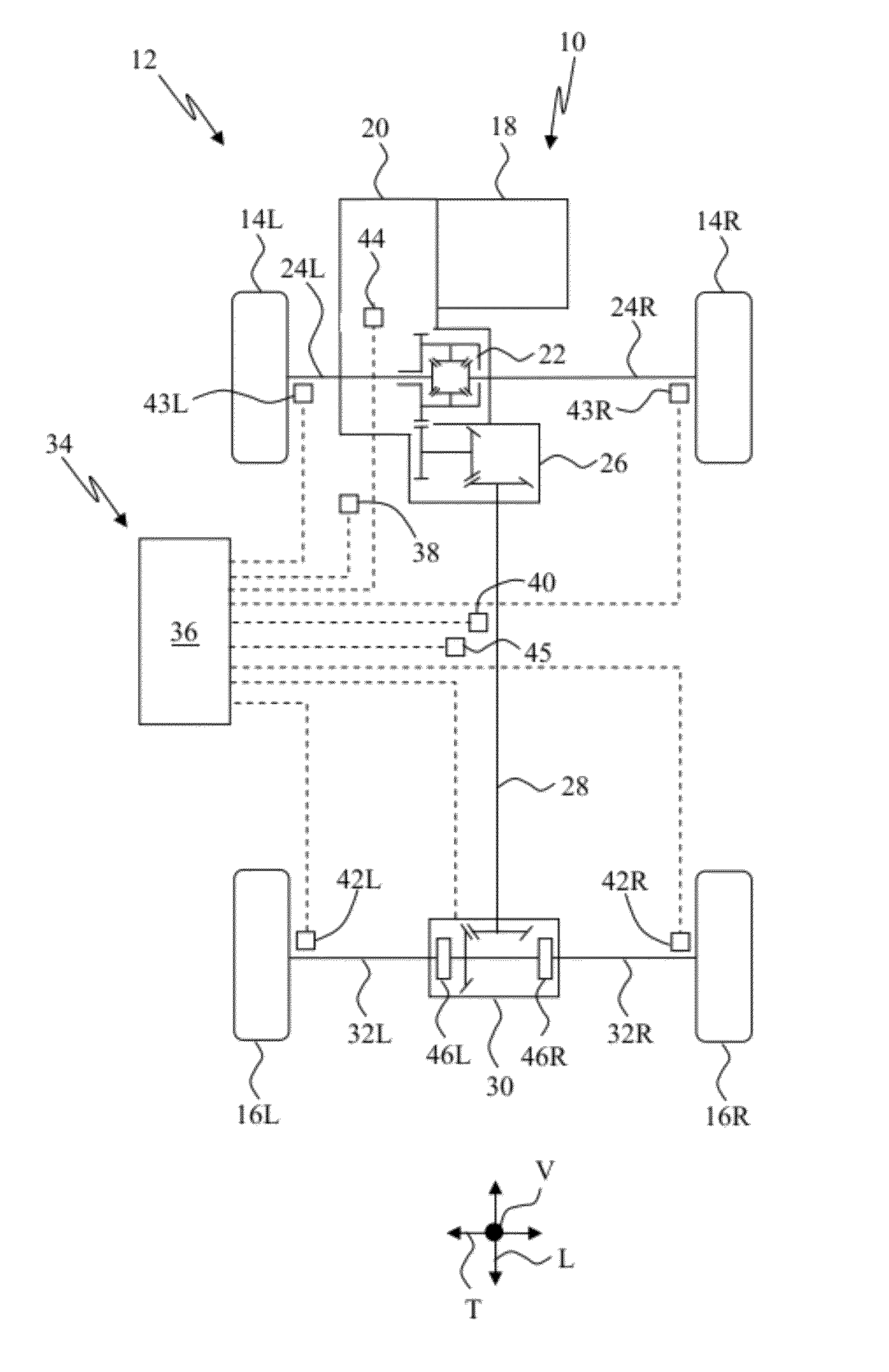
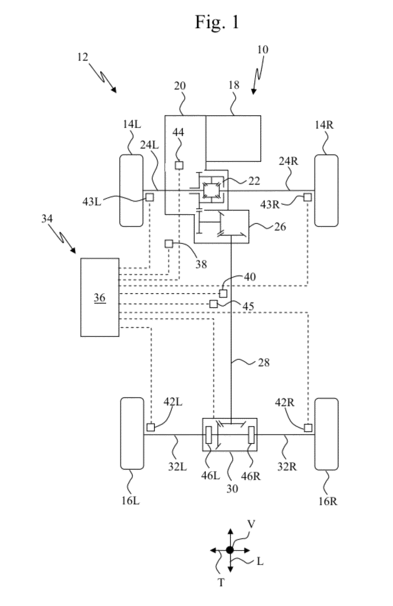
[0028]FIG. 1 illustrates an embodiment of a powertrain 10 for a vehicle 12, where the vehicle 12 has a longitudinal direction L, a transverse (or lateral) direction T perpendicular to the longitudinal direction, and a vertical direction V perpendicular to both the longitudinal direction L and the transverse direction T. The powertrain 10 can be configured as an on-demand, part-time, all-wheel drive system in accordance with the principles of the disclosed subject matter. This exemplary powertrain 10 can be configured such that the steerable front wheels 14L, 14R are the primary drive wheels and the rear wheels 16L, 16R are selectively driven automatically when additional tractive effort is appropriate for the given vehicle conditions. However, the powertrain 10 can be configured such that the rear wheels 16L, 16R are the primary drive wheels and the front wheels 14L, 14R are driven only when additional tractive effort is appropriate. In other embodiments, the powertrain 10 can be co...


PUM


Abstract

A system for determining an angular position of a steerable wheel of a vehicle can include a plurality of sensors and a controller in electrical communication with each of these sensors. The controller can be configured to compare a first data set and a second data set to respective straight path conditions, wherein the first data set includes data from a first set of the sensors and the second data includes data from a second set of the sensors. The controller can be configured to determine a substantially straight path of travel condition when the comparison of at least one of the first data set and the second data set satisfies the respective straight path conditions, and can then associate that data acquired from the steering angle sensor(s) with a neutral position.

Description

CROSS REFERENCE TO RELATED APPLICATIONS[0001]This application claims the priority benefit under 35 U.S.C. §120 and is a continuation-in-part of co-pending U.S. patent application Ser. No. 12 / 857,359 filed on Aug. 16, 2010.BACKGROUND[0002]1. Field[0003]The presently disclosed subject matter relates to devices, systems, and processes useful as an assistance feature to supplement an operator's control input to a vehicle.[0004]2. Description of the Related Art[0005]Vehicles have typically included a system(s) that assists an operator's input for the control of the vehicle. This assistance can supplement the operator's control of the vehicle to enhance comfort for the operator / passenger(s) and / or to enhance dynamic performance of the vehicle. Examples of an operator assistance system can include, but are not limited to, power steering systems, anti-lock braking systems (ABS), traction control systems (TCS), and stability assistance systems (aka, VSA, VSC or ESP)—which can be, active susp...

Claims


Application Information

Patent Timeline
IPC IPC(8): G06F7/00
CPCB62D15/0215B62D15/0245B62D15/024B60W10/20B62D15/02B62D15/021
Inventor TURNER, STEVEN PAUL
Owner HONDA MOTOR CO LTD
Why Eureka
Try Eureka