Fluid tube

Inactive Publication Date: 2012-02-23
LIU YING SHU
View PDF5 Cites 0 Cited by
  • Summary
  • Abstract
  • Description
  • Claims
  • Application Information

AI Technical Summary

Benefits of technology

[0008]The present invention has been accomplished under the circumstances in view. It is one object of the present invention to provide a fluid tube carrying a fluid, which well seals the contained fluid against floating or evaporation, facilitating quick application.
[0009]To achieve this and other objects of the present invention, a fluid tube comprises a tube having two opposing open ends, a fluid contained in the tube, a sealing cap heat-sealed to one end of the tube, and a plug cap capped on the other end of the tube to seal the fluid in the tube and to protect the fluid against evaporation.
[0010]Further, the sealing cap comprises a plurality of dentations b

Problems solved by technology

During application, the fluid may drop from the stick applicator accidentally, causing contamination.
However, when breaking the breakable neck of the tubular container body, the fluid may be splashed onto the surrounding

Method used


Image

  • Fluid tube
  • Fluid tube
  • Fluid tube

Examples


Embodiment Construction

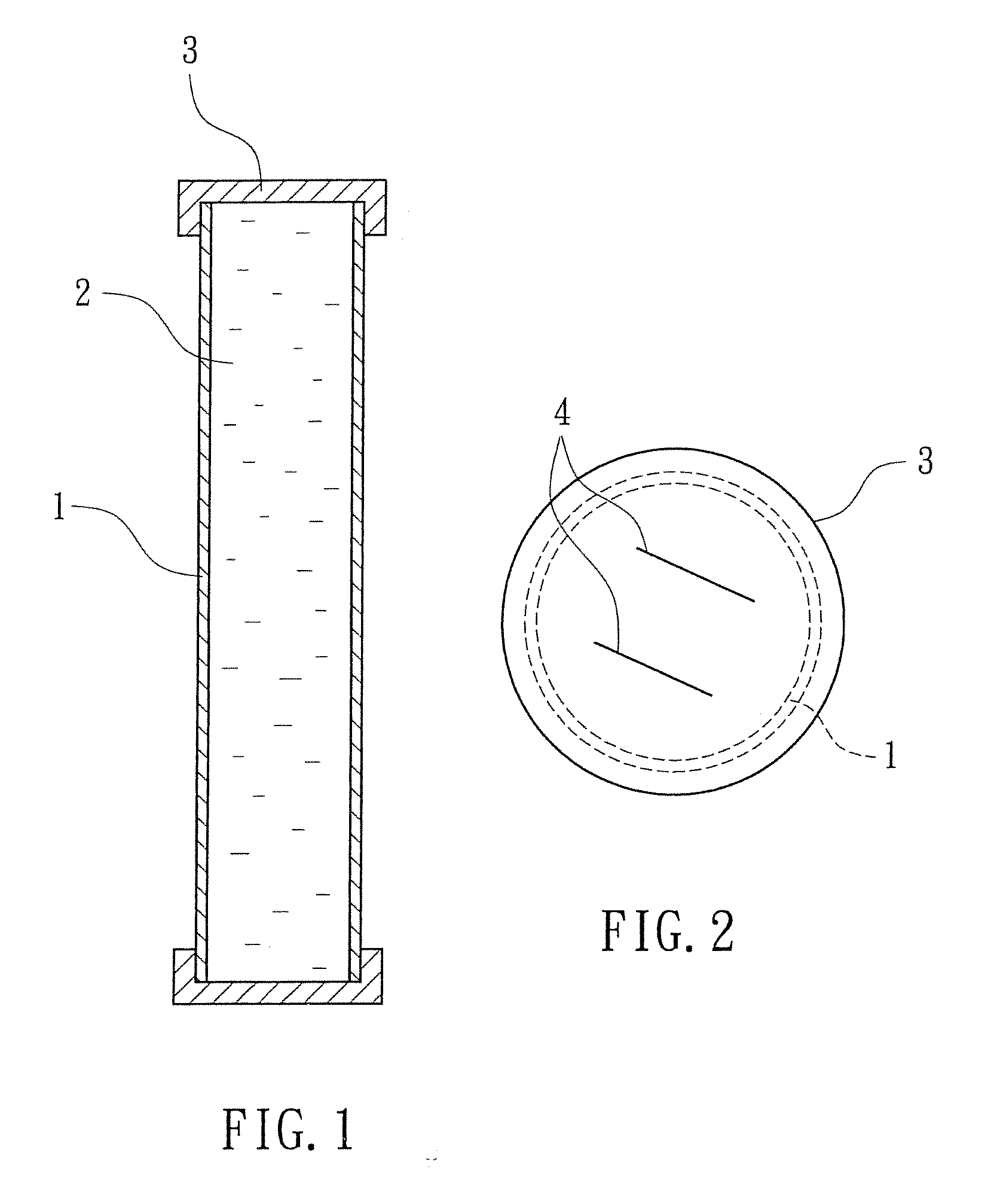
[0017]Referring to FIGS. 1 and 2, a fluid tube in accordance with a first embodiment of the present invention is shown comprising a tube 1, a fluid 2 that can be, for example, a fluid medicine, alcohol, a cosmetic fluid carried in the tube 1, and a sealing cap 3 capped on one open end (or each of two opposite open ends) of the tube 1 to protect the fluid 2 against the effect of the outside atmospheric pressure. The sealing cap 3 has dentations 4.

[0018]When using the fluid tube, impart a pressure to the sealing cap 3 to break the dentations 4 with, for example, the thumb, letting the atmospheric pressure enter the tube 1 to force the contained fluid 2 downwardly along the tube 1 toward the outside for application when the tube 1 is kept in vertical or inclined.

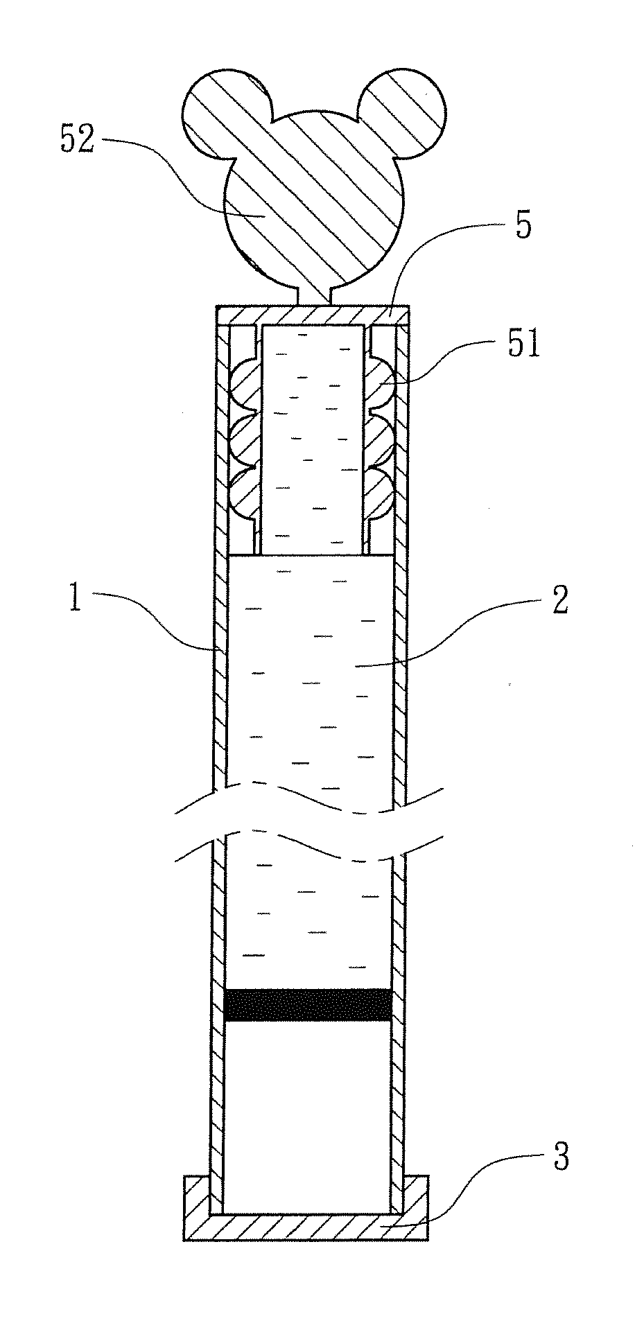
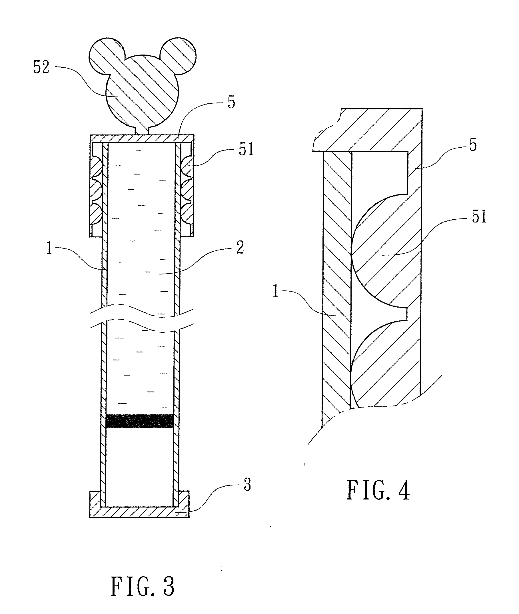
[0019]Referring to FIGS. 3 and 4, a fluid tube in accordance with a second embodiment of the present invention is shown comprising a tube 1, a fluid 2 carried in the tube 1, a sealing cap 3 heat-sealed to one open end of the tu...


PUM


Abstract

A fluid tube includes a tube, a fluid, for example, a fluid medicine, alcohol or cosmetic fluid carried in the tube, a sealing cap heat-sealed to one end of the tube and having dentations breakable for letting the atmospheric pressure enter the tube, and a plug cap capped on the other end of the tube to seal the fluid in said tube and having rounded inside protrusions forced into friction engagement with the tube.

Description

BACKGROUND OF THE INVENTION[0001]1. Field of the Invention[0002]The present invention relates to fluid containers and more particularly, to a fluid tube for carrying a fluid and keeping it well sealed for easy application.[0003]2. Description of the Related Art[0004]Many fluid containers with an attached applicator stick have been disclosed and are commercially available for electronic industrial cleaning application, cosmetic application and management or skin treatment application. The applicator stick of a fluid container is attached to the cap of the container and dipped in the contained fluid. During application, the fluid may drop from the stick applicator accidentally, causing contamination.[0005]There is known a fluid container comprising a tubular container body having a close end and an open end, and a seal sealing the open end. The tubular container body has a breakable neck. When in use, the user can break the breakable neck, enabling the fluid to flow out of the tubular...

Claims


Application Information

Patent Timeline
IPC IPC(8): A61F13/40
CPCB65D39/0005B65D39/16B65D59/06B65D59/02B65D47/2031
Inventor LIU, YING-SHU
Owner LIU YING SHU
Why Eureka
Try Eureka