
Ride Height Control System and Method for Controlling Load Distribution at Target Ride Height in a Vehicle Suspension System

a technology of ride height control system and target ride height, which is applied in the direction of cycle equipment, transportation and packaging, instruments, etc., can solve the problems of cross-jacking condition of suspension system with existing ride height control system, possible compounding of problems, and affecting the stability of suspension system,

Active Publication Date: 2012-02-23
FOURTH FLOOR ASSOCS
View PDF3 Cites 12 Cited by
  • Summary
  • Abstract
  • Description
  • Claims
  • Application Information

AI Technical Summary

Problems solved by technology

As a result, different pressures in the suspension system at different wheel locations can occur and thus different loads are supported by the suspension system at different wheel locations, unnoticed by the operator.
These problems may be compounded in vehicles with a larger number of wheels (e.g., eight wheel vehicles) such as those used by the military.
One problem that occurs in vehicle suspension system with existing ride height control systems is a cross-jacking condition.
Under a cross-jacking condition, a load imbalance exists at the wheel locations even though the vehicle may be at the target ride height.
These load imbalances may adversely affect the handling of the vehicle, for example, as a result of different tractions on the tires and / or different suspension response at the different wheel locations.
Another problem may occur in vehicle suspension systems with existing ride height control systems as a result of a wheel displacement condition.
The position at the other locations may then be independently adjusted to maintain the target ride height, which may result in different pressures and loads at the different wheel locations.
When the vehicle is moved back to a relatively flat surface after these adjustments, the loads may be unbalanced and the ride height may initially need to be readjusted.
These load imbalances and ride height adjustments caused by wheel displacement conditions may also adversely affect the vehicle performance and handling.

Method used


Image

  • Ride Height Control System and Method for Controlling Load Distribution at Target Ride Height in a Vehicle Suspension System
  • Ride Height Control System and Method for Controlling Load Distribution at Target Ride Height in a Vehicle Suspension System
  • Ride Height Control System and Method for Controlling Load Distribution at Target Ride Height in a Vehicle Suspension System

Examples


Embodiment Construction

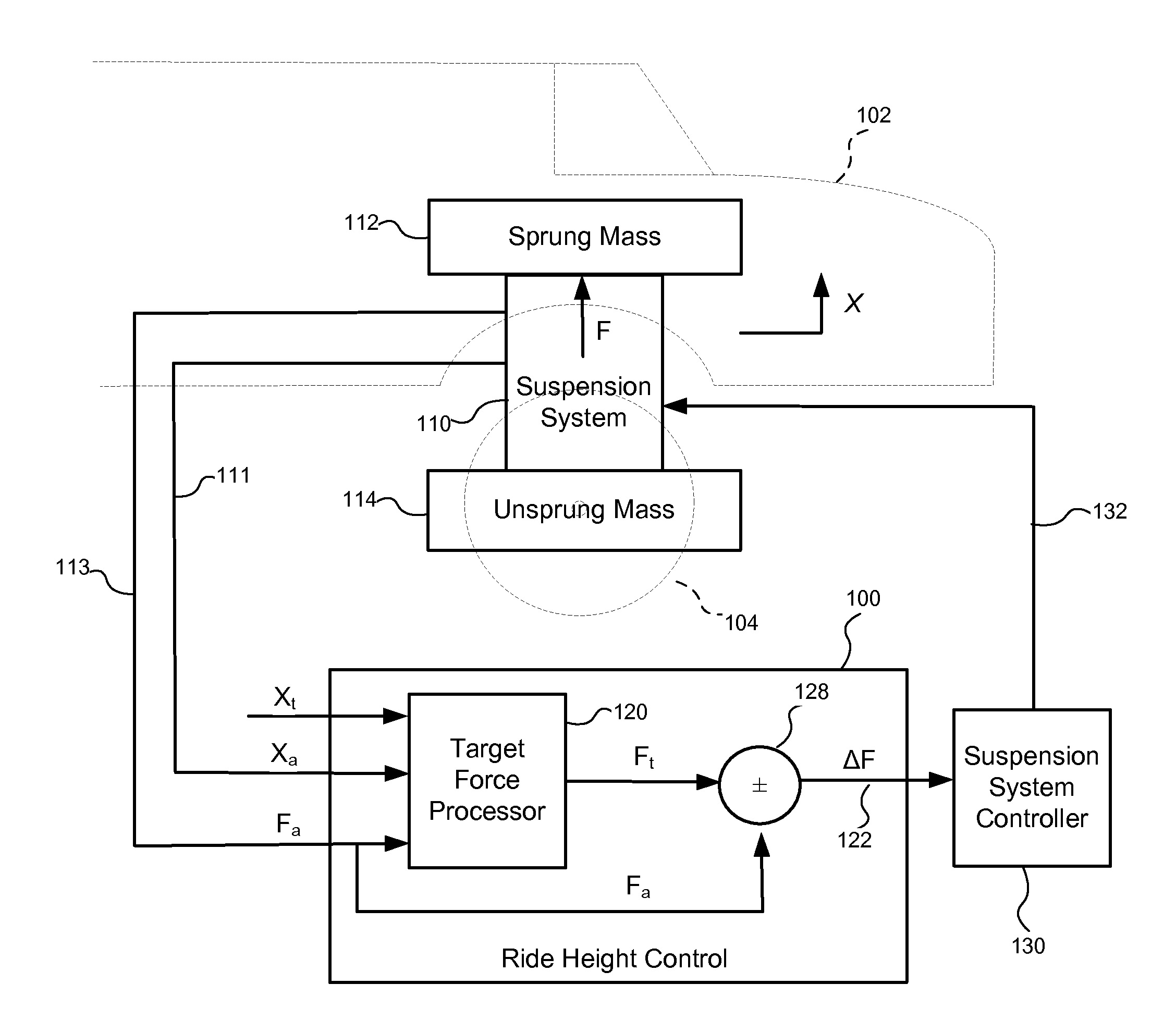
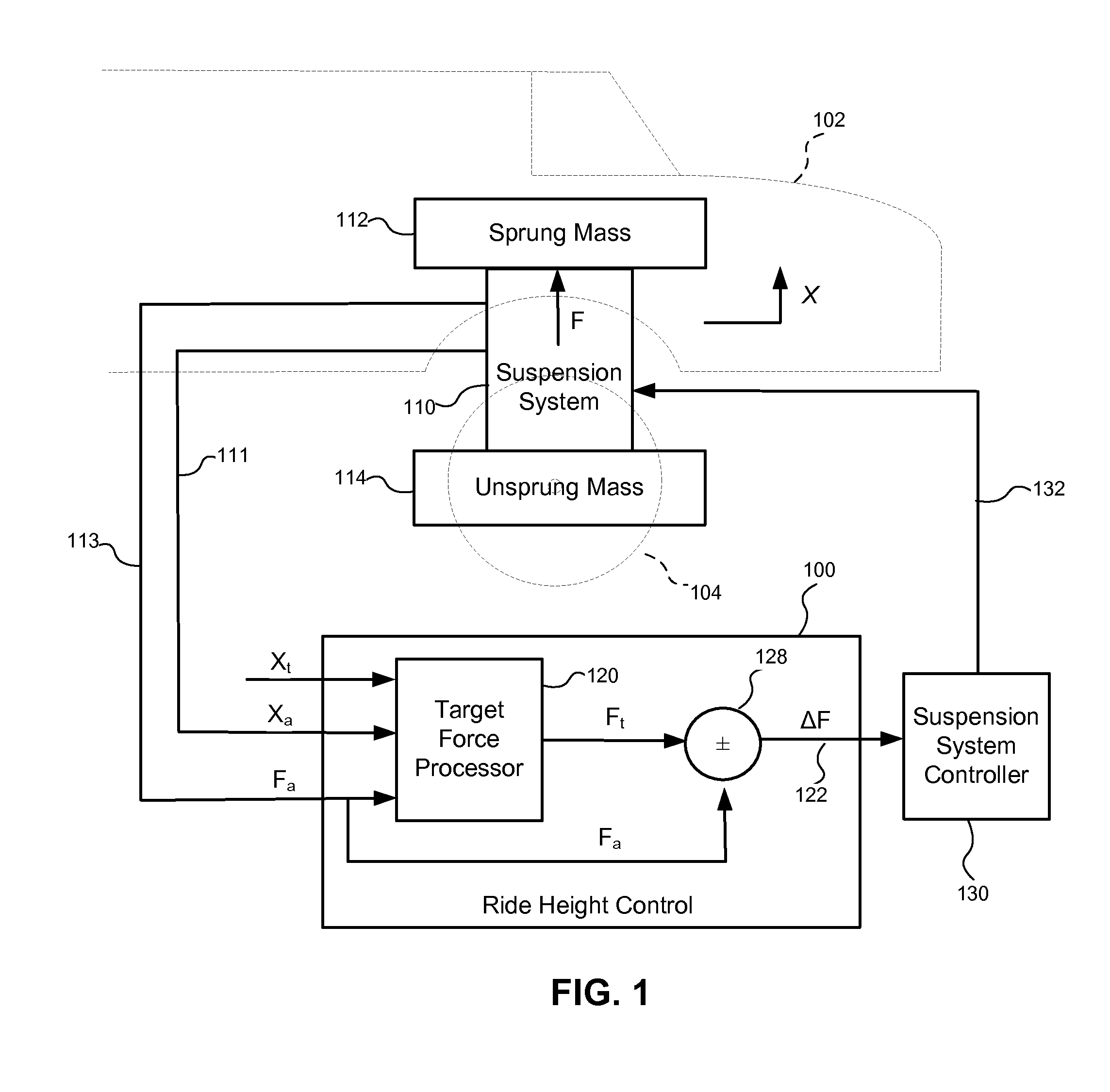
[0021]A ride height control system and method, consistent with embodiments described herein, may be used to control load distribution at wheel locations in a vehicle suspension system at target ride height. Load distribution may be controlled by adjusting the forces applied by the suspension system at respective wheel locations while maintaining a target ride height. In an exemplary air spring suspension system or hydropneumatic suspension system, the applied forces may be adjusted by adjusting the pressure in the suspension system at the respective wheel locations.

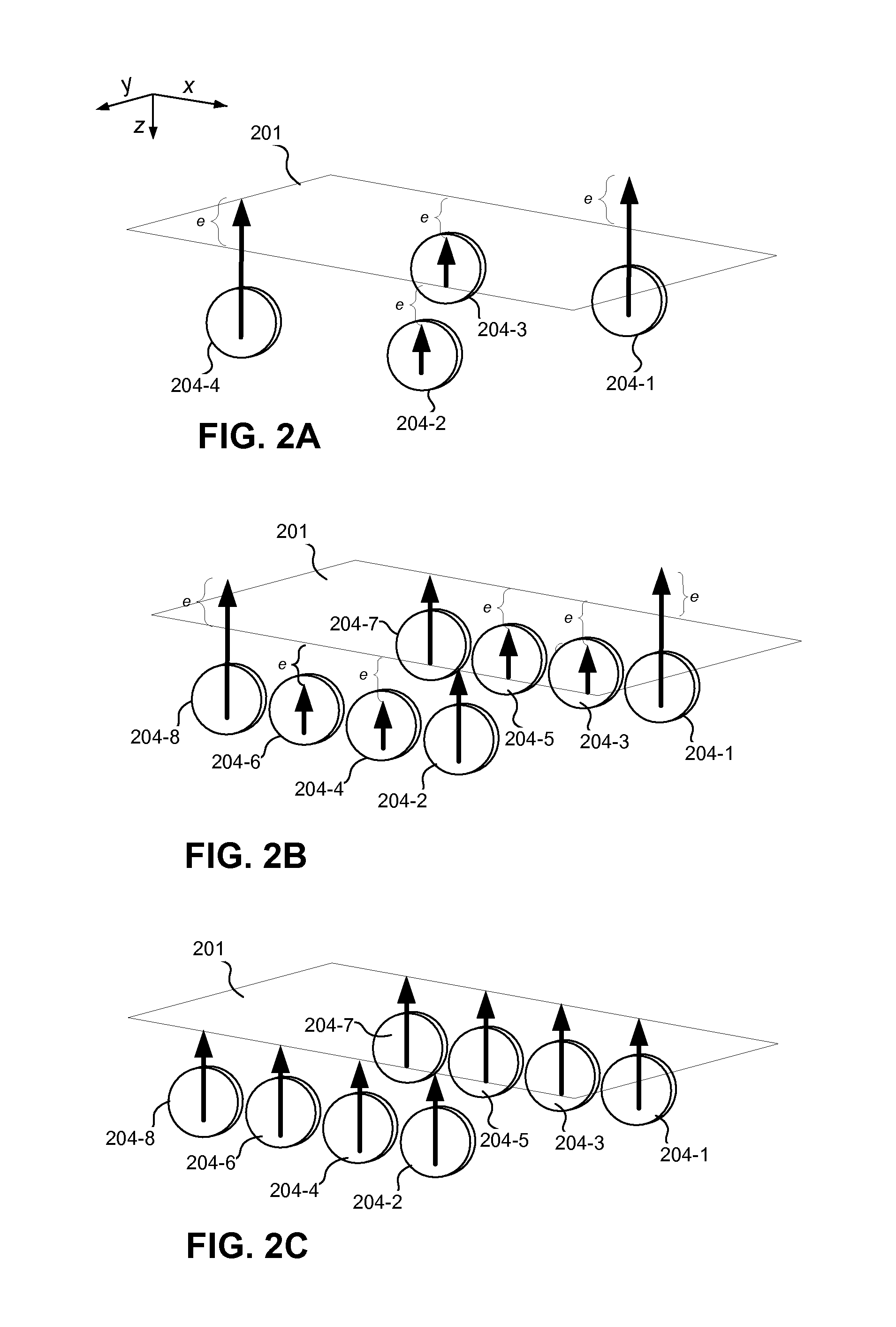
[0022]In one embodiment, the ride height control system and method may determine and establish balanced target ride height (TRH) forces to be applied at the wheel locations of the vehicle to prevent a cross-jacking condition. The balanced TRH forces may be planar reaction forces having force vectors whose tips collectively best fit a plane. In another embodiment, the ride height control system and method may also determin...


PUM


Abstract

A ride height control system and method may be used to control load distribution at wheel locations in a vehicle suspension system at target ride height. Load distribution may be controlled by adjusting the forces applied by the suspension system at respective wheel locations while maintaining a target ride height. In an exemplary air spring suspension system or hydropneumatic suspension system, the applied forces may be adjusted by adjusting the pressure in the suspension system at the respective wheel locations. The ride height control system and method may determine and establish balanced target ride height forces (e.g., planar forces) to be applied at the wheel locations of the vehicle to prevent a cross-jacking condition. The ride height control system and method may also determine and establish target ride height forces for a vehicle on an uneven surface to prevent imbalances caused by wheel displacement.

Description

TECHNICAL FIELD[0001]The present invention relates to vehicle suspension systems and more particularly, to a ride height control system and method for controlling load distribution at target ride height in a vehicle suspension system.BACKGROUND INFORMATION[0002]Vehicle suspension systems may include ride height control systems for controlling the height of a vehicle relative to a surface on which the vehicle rides. Existing ride height control systems generally operate based on the position of the sprung mass (e.g., the vehicle chassis) relative to the unsprung mass (e.g., the vehicle wheels or axle). A ride height control system may monitor and adjust the position at each wheel location to provide a target ride height. The target ride height may be controlled by the operator manually, for example, by selecting pre-set target ride heights. The target ride height may also be controlled dynamically based on vehicle operating conditions (e.g., speed).[0003]Ride height control may be pr...

Claims


Application Information

Patent Timeline
IPC IPC(8): B60G17/018B60G17/044
CPCB60G17/018B60G17/0424B60G2600/182B60G2400/51B60G2500/20B60G2400/252
Inventor LARKINS, WILLIAM T.LANZILOTTA, EDWARDHARTY, DAMIAN
Owner FOURTH FLOOR ASSOCS
Learn More