Dual-purpose spin dry mop bucket

Inactive Publication Date: 2012-03-01
CHU SHU HSUN
View PDF1 Cites 23 Cited by
  • Summary
  • Abstract
  • Description
  • Claims
  • Application Information

AI Technical Summary

Benefits of technology

[0013]Thus, when compared to conventional spin buckets, the invention provides an additional agitator for stirring and rubbing the mop head to remove dirt and solid matters from the mop head. Further, the same power source for rotating the spin basket is utilized to r

Problems solved by technology

Rinsing the mop head 61 in this manner cannot remove dirt from it effectively.
Therefore, this prior art mop bucket design can simply spin dry the mop but cannot effectively clean the mop head.
Further, dirt deposited in the bottom of the vertical rinsing space of the m

Method used


Image

  • Dual-purpose spin dry mop bucket
  • Dual-purpose spin dry mop bucket
  • Dual-purpose spin dry mop bucket

Examples


Embodiment Construction

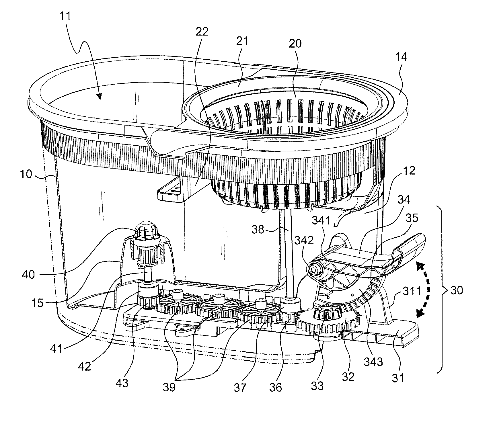
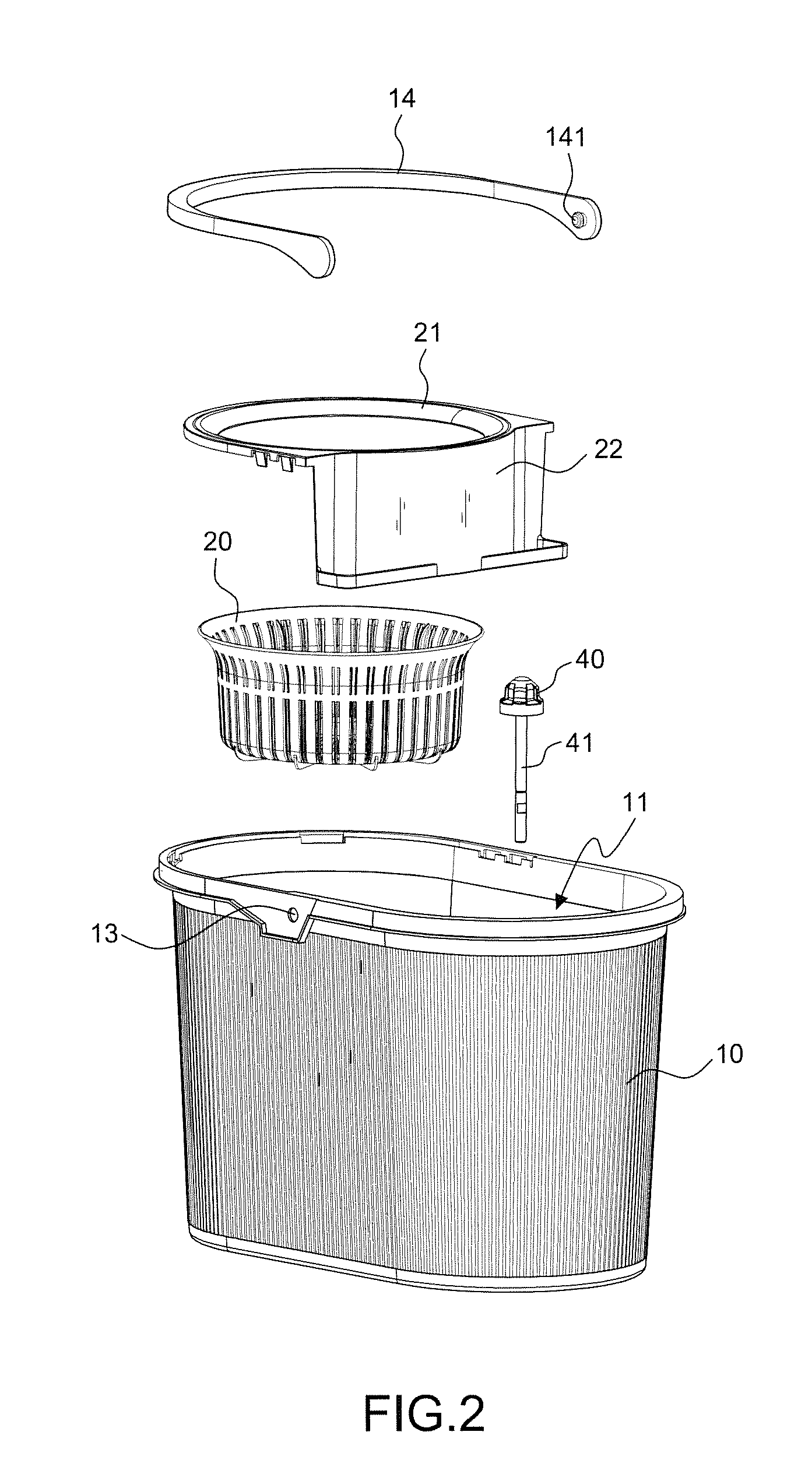
[0021]Referring to FIGS. 2 to 7, a dual-purpose spin dry mop bucket in accordance with the present invention comprises a housing 10 includes a top open side 11, a recessed accommodation area 12 in a front part of a bottom side of the housing 10, a driving mechanism 30 mounted in the recessed accommodation area 12 and adapted for rotating a spin basket 20. In this preferred embodiment, a carrying handle 14 as shown in FIG. 2 arranged at the top side of the housing 10. The carrying handle 14 is an arched bar having a pivot rod 141 located on each of the two distal ends and respectively pivotally coupled to a respective pivot hole 13 at the housing 10.

[0022]With reference to FIGS. 2 and 3, a water retaining ring 21 is mounted at the top side of the spin basket 20 mounted in the housing 10 and the recessed accommodation area 12, having a water baffle 22 downwardly suspending at one side for stopping water from splashing on the surroundings outside the housing 10.

[0023]With reference to ...


PUM


Abstract

The present invention relates to mop buckets, including a housing, a spin basket mounted in the housing, and a driving mechanism rotating the spin basket. The present invention uses the driving mechanism to rotate an agitator for stirring and rubbing the mop head to remove dirt and solid matters and to synchronously rotate a spin basket for drying the mop head of the mop. Further, the present invention utilizes gears and one-way couplings to transfer driving force for rotating the agitator and the spin basket at the same time, saving much installation space and facilitating mop cleaning and drying operations.

Description

BACKGROUND OF THE INVENTION[0001]1. Field of the Invention[0002]The present invention relates to mop buckets and more particularly, to a dual-purpose spin dry mop bucket, which can clean the mop head as well as spin-dry the mop head.[0003]2. Description of the Related Art[0004]Mop is a tool commonly used for floor cleaning. A mop bucket may be used with a mop for removing water from the mop. A conventional mop bucket uses squeezer means to squeeze water out of the cotton strips of the mop. FIG. 1 illustrates a mop bucket 50 constructed according to Taiwan Utility Model M338534. According to this design, the mop bucket 50 comprises a housing 51, a mount 52, and a rotating unit 53 which comprises a support device, a rotating shaft, a transmission mechanism and a push bar unit that are coupled to one another for rotating a spin basket 54 to spin-dry the cotton or micro-fiber mop head 61 of the mop 60 inserted therein. This design of mop bucket 50 has drawbacks. It simply provides a ver...

Claims


Application Information

Patent Timeline
IPC IPC(8): A47L13/58
CPCA47L13/58
Inventor CHU, SHU-HSUN
Owner CHU SHU HSUN
Why Eureka
Try Eureka