Robot arm mechanism and robot using the same

Inactive Publication Date: 2012-03-01
HONG FU JIN PRECISION IND (SHENZHEN) CO LTD +1
View PDF16 Cites 17 Cited by
  • Summary
  • Abstract
  • Description
  • Claims
  • Application Information

AI Technical Summary

Problems solved by technology

This may cause the motor encoder of the robot to send an alarm or even cause the robot to stop working.
However, the existing coolin

Method used


Image

  • Robot arm mechanism and robot using the same
  • Robot arm mechanism and robot using the same
  • Robot arm mechanism and robot using the same

Examples


Example

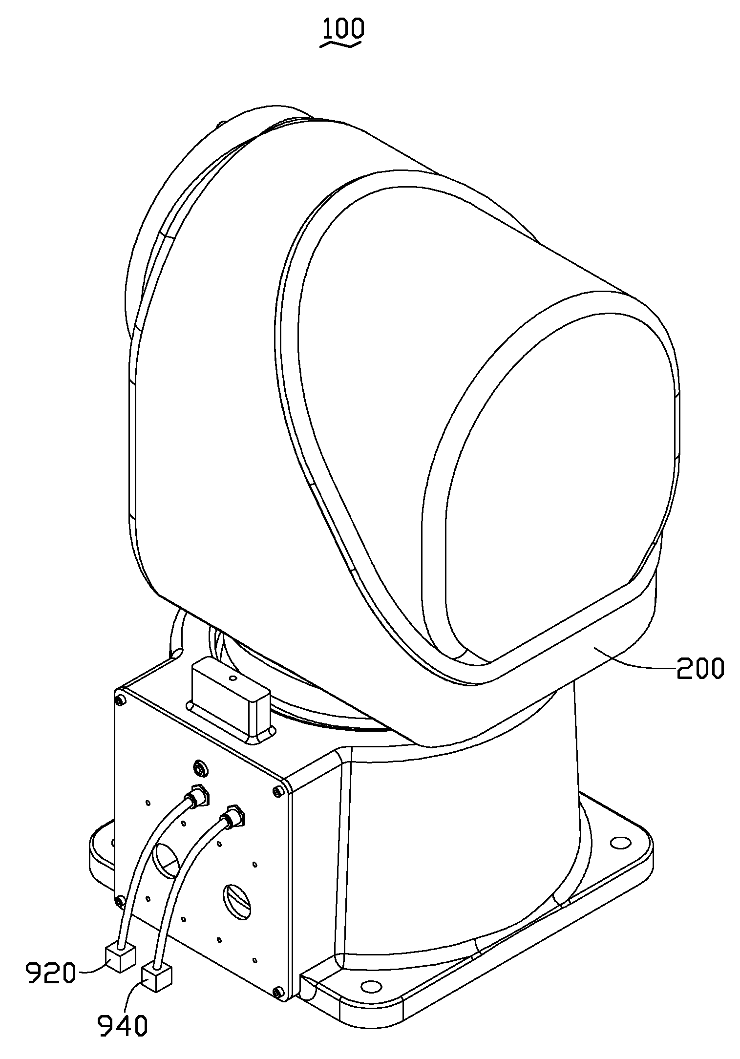
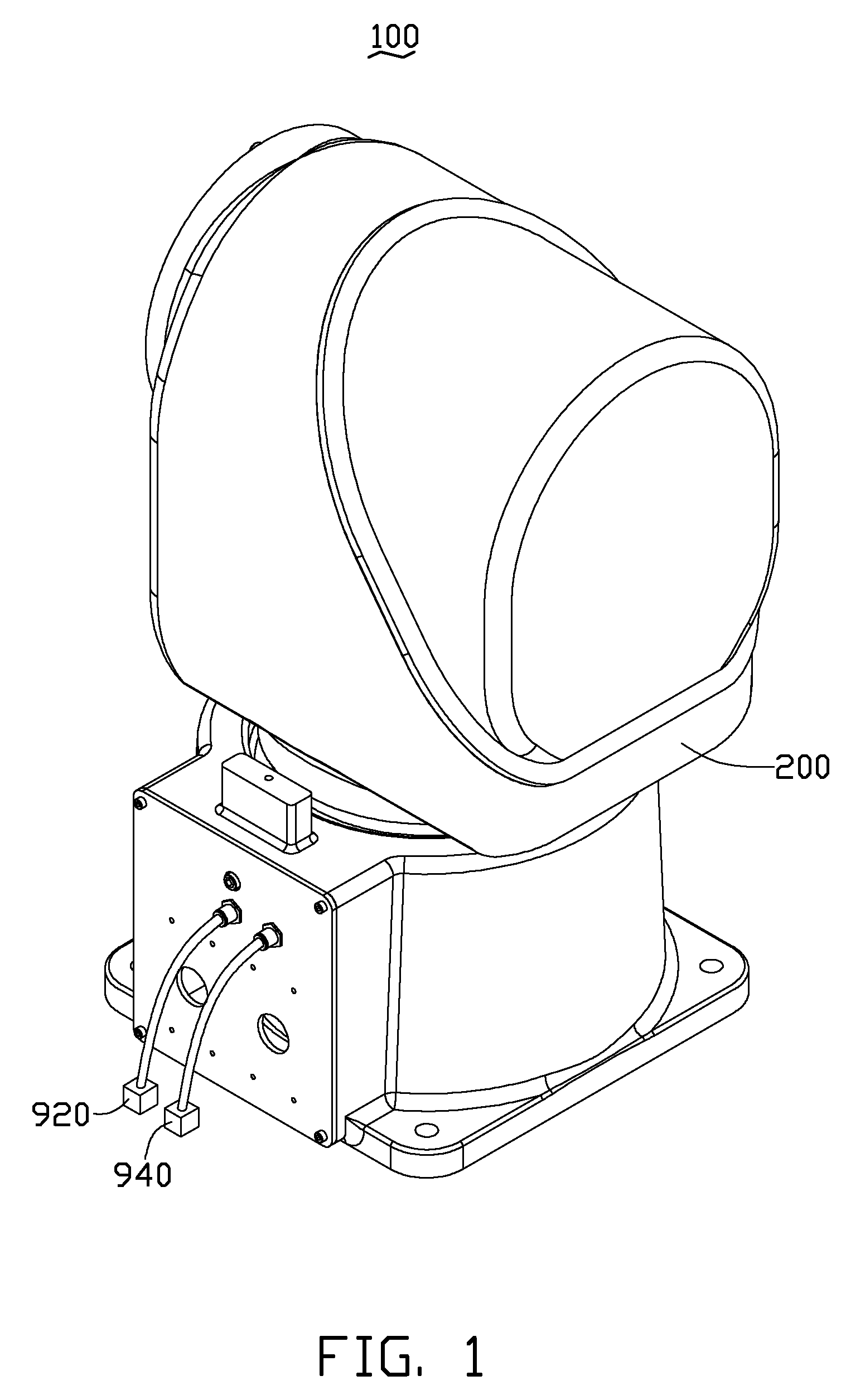
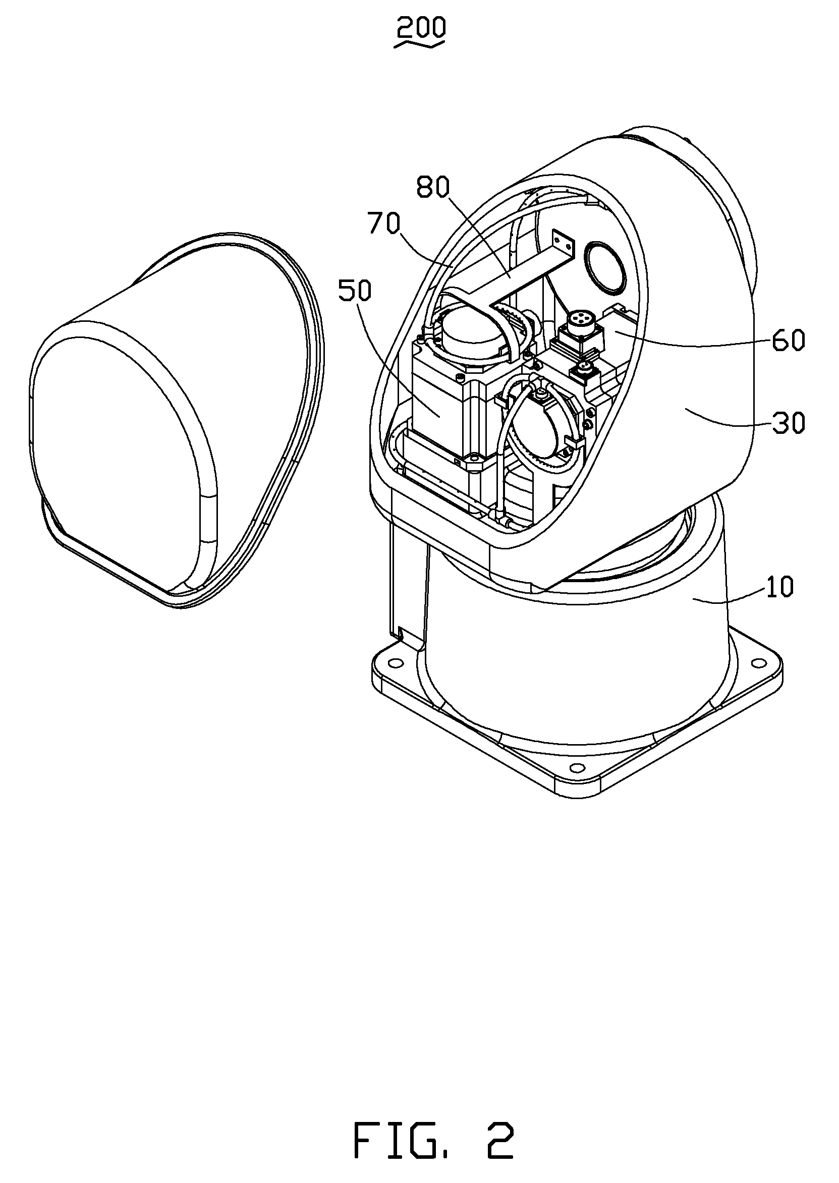
[0012]Referring to FIGS. 1 through 4, an embodiment of a robot 100 includes a robot arm mechanism 200, an air source 920 and an air evacuating equipment 940. The robot arm mechanism 200 includes a first shaft assembly 10, a second shaft assembly 30 rotatably assembled with the first shaft assembly 10, a first motor 50, a second motor 60, an air tubing assembly 70 and a support member 80. The first and second motors 50, 60 are selectively assembled within the first shaft assembly 10 and / or the second shaft assembly 30. In the illustrated embodiment, the first and second motors 50, 60 are both assembled within the second shaft assembly 30. The air tubing assembly 70 is assembled within the first shaft assembly 10 and / or the second shaft assembly 30, and surrounds the first and second motors 50, 60, and further connects with the air source 920 and the air evacuating equipment 940 for cooling down the inner temperature of the robot 100.

[0013]The first shaft assembly 10 includes a base 1...


PUM


Abstract

A robot arm mechanism includes a first shaft assembly, a second shaft assembly, a first motor, a second motor, and an air tubing assembly. The second shaft assembly is rotatably assembled with the first shaft assembly. The first motor is selectively assembled within the first shaft assembly or the second shaft assembly. The air tubing assembly is assembled within the first shaft assembly or the second shaft assembly, and surrounds the first motor for cooling down the first motor, surrounds the second motor for cooling down the second motor, and cooling down the inner temperature of the robot. A robot using the robot arm mechanism is further provided.

Description

BACKGROUND[0001]1. Technical Field[0002]This disclosure relates to robotics, and particularly, to a robot arm mechanism and a robot using the same.[0003]2. Description of Related Art[0004]Presently, robots are widely used in automated production settings A commonly used robot generally includes a plurality of rotary shafts and a plurality of motors assembled with the robot for driving the rotary shafts to rotate. In use, the motors generate much heat thereby sharply increasing the internal temperature within the robot. This may cause the motor encoder of the robot to send an alarm or even cause the robot to stop working. Therefore, cooling fans are assembled within the robot to dissipate and carry the heat to outside of the robot. However, the existing cooling fans occupy a relatively large amount of space within the robot, which means that the inner structure of the robot is made larger.[0005]Therefore, there is room for improvement in the art.BRIEF DESCRIPTION OF THE DRAWINGS[0006...

Claims


Application Information

Patent Timeline
IPC IPC(8): B25J18/00
CPCB25J19/0054Y10T74/20311Y10T74/20317Y10T74/20305
Inventor LONG, BO
Owner HONG FU JIN PRECISION IND (SHENZHEN) CO LTD
Why Eureka
Try Eureka