

Reciprocating-type variable-speed pedal structure for scooter
a variable-speed pedal and scooter technology, applied in the field of scooters, can solve the problems of easy fatigue of repeated lifting return, low pedaling power, and low stability of use of the rider, and achieve the effects of low motion range, low center of gravity of the rider, and low resistance to pedaling
- Summary
- Abstract
- Description
- Claims
- Application Information
AI Technical Summary
Benefits of technology
Problems solved by technology
Method used
Image

Examples
example 1
Flexible Plate Return Single Power Reciprocating Variable Speed Pedal structure
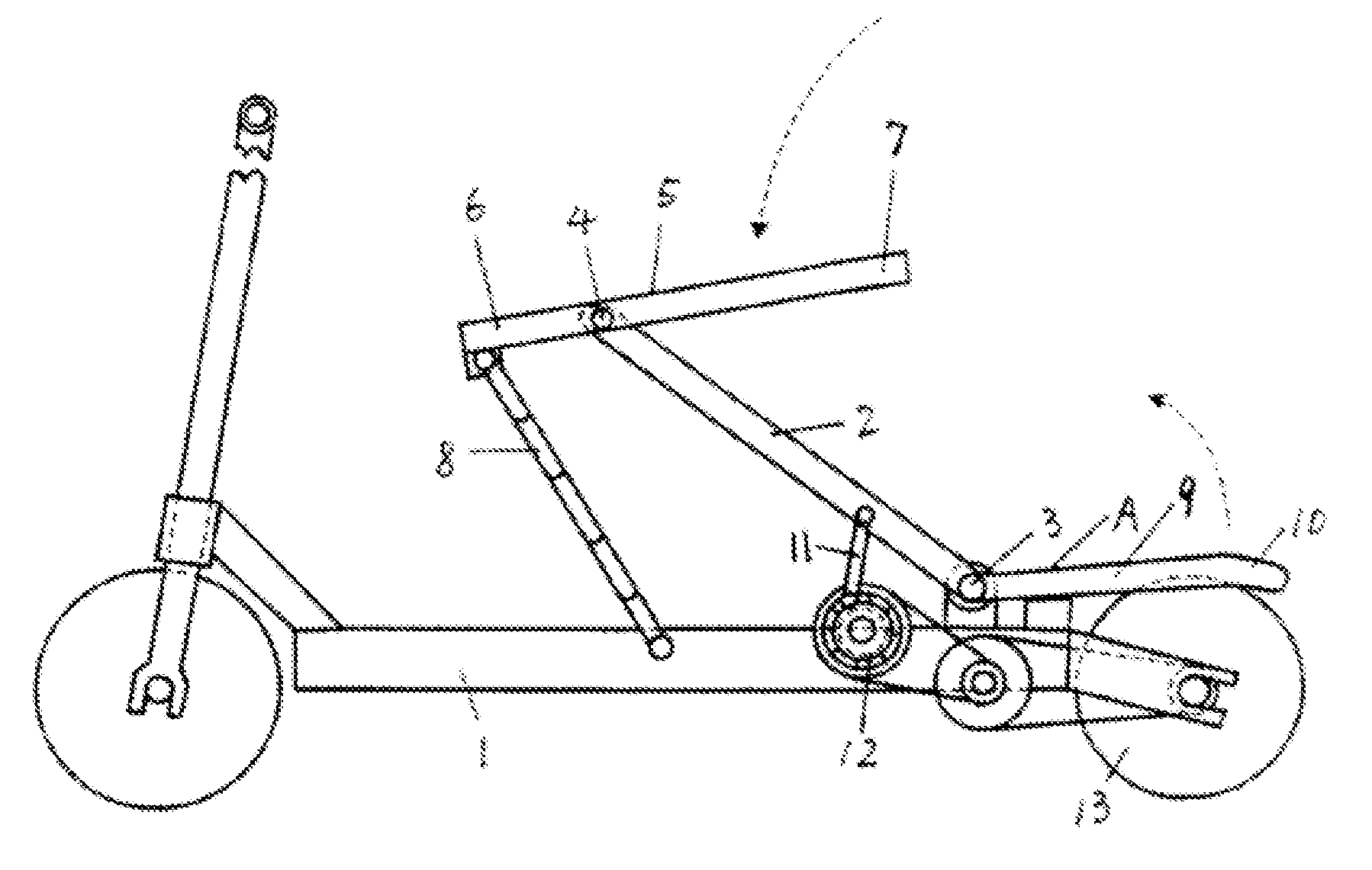
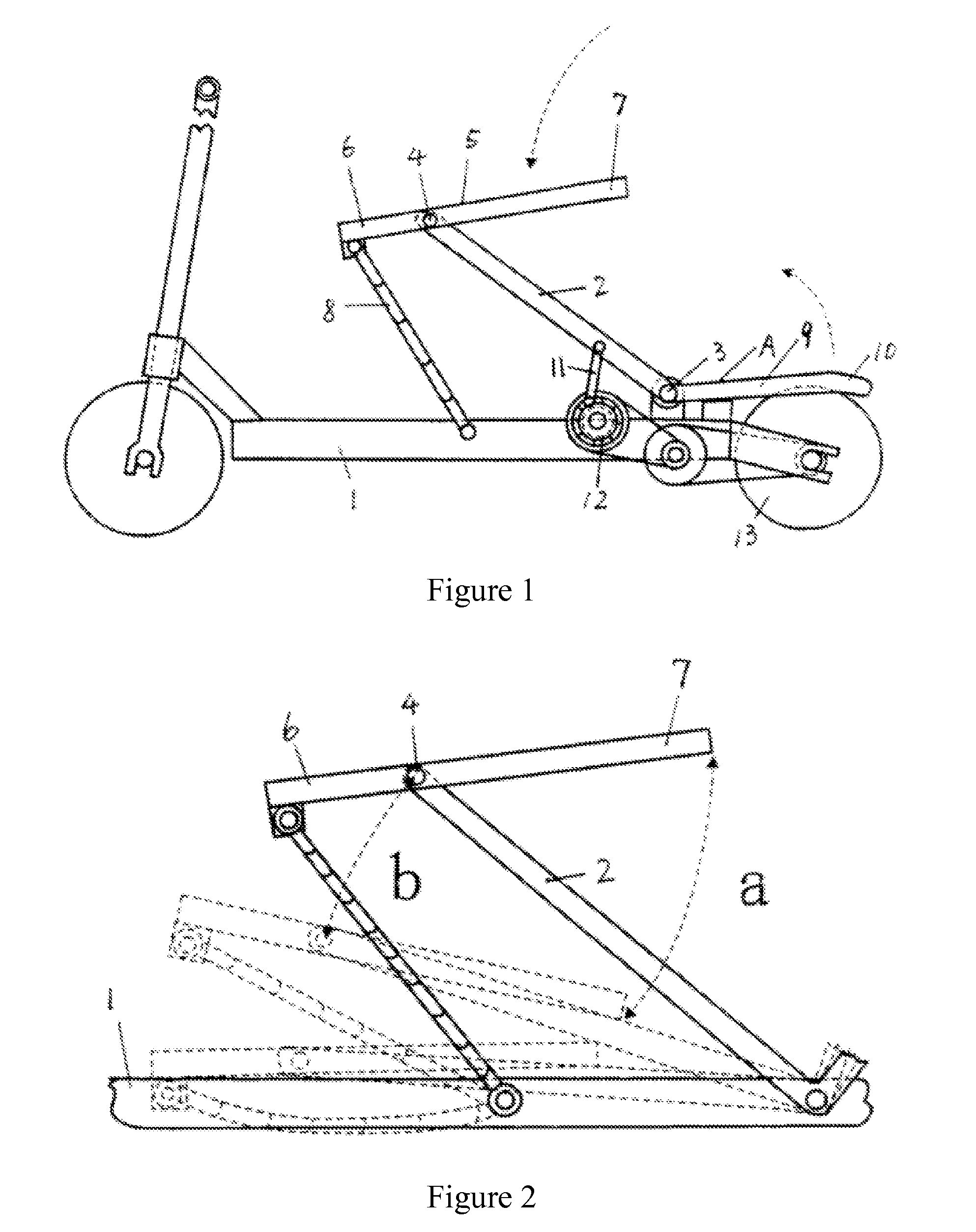
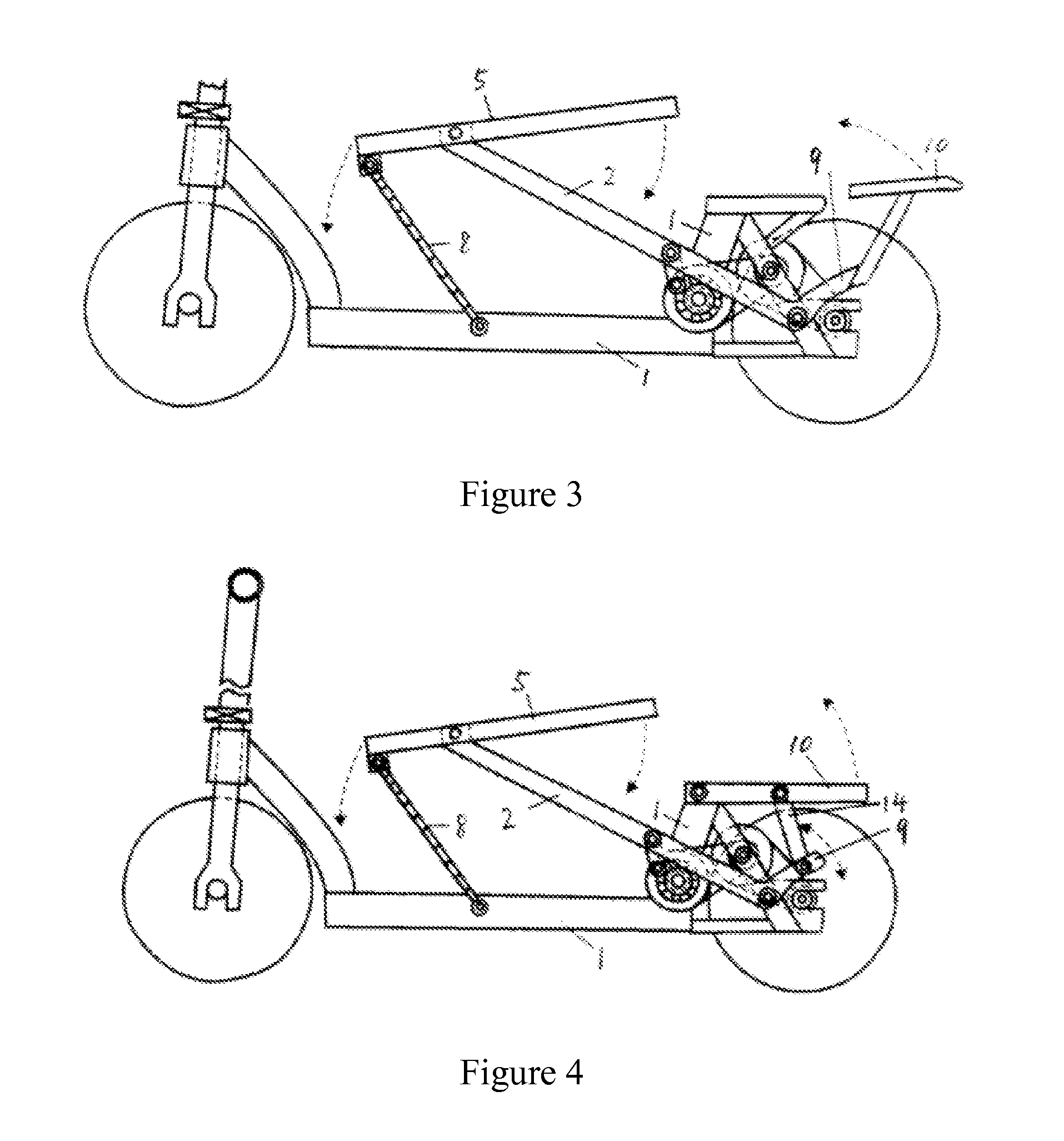
[0034]The reciprocating variable speed pedal structure of the example is a flexible plate return single power reciprocating variable speed pedal structure as shown in FIG. 1. The reciprocating variable speed pedal structure comprises a power pressure bar 2 movably connected to a scooter bracket 1, the power pressure bar 2 is movably connected to the scooter bracket 1 through a shaft 3 actually, an upper end of the power pressure bar 2 is movably connected with a movable pedal 5 through a shaft 4 and divides the movable pedal into a limit end 6 and a labor-saving end 7, a movable connecting member 8 capable of limiting the motion range of the movable pedal is arranged between the front part of the movable pedal limit end and the scooter bracket and is of a pull cord or slide fastener structure. A power pressure bar return mechanism A is composed of a return pressure bar 9 and a return pedal 10 formed by an...
example 2
Flexible Plate Return Double Power Reciprocating Variable Speed Pedal Structure
[0038]The reciprocating variable speed pedal structure in this example is of flexible plate return double power reciprocating variable speed pedal structure (see FIGS. 16-19). In FIG. 16, there are two sets of the power pressure bars 2 (front and rear) which are integrated to directly form the flexible plate structure. During the up and down linkage, the power pressure bars can act as a return mechanism for each other and are provided with two sets of independent ratchet systems for power output which are also known as a heteraxial double ratchet structure. FIG. 17 has the basically same structure as FIG. 16, but a coaxial double ratchet structure is employed for the power output. In FIG. 18, there are also two sets of power pressure bar 2 (front and rear) which are coaxially and movably connected to the scooter bracket, a connecting return spring 19 is arranged therebetween, thus the two power pressure b...
example 3
Elastic Return Single Power Reciprocating Variable Speed Pedal Structure
[0040]The reciprocating variable speed pedal structure in this example is of an elastic return single power reciprocating variable speed pedal structure (see FIG. 21). In FIG. 21, a tension spring 21 or a torsion spring 22 (FIG. 22) can be used as the return mechanism A of the power pressure bar 2. Of course, FIGS. 21-22 can use a pressure spring, an elastic cord as shown in FIG. 23 or a shoe hook and shoe cover structure as shown in FIGS. 25-26. In fact, the return mechanisms in all the solutions in example 1 can be of the tension spring, the pressure spring, the torsion spring, the elastic cord, the shoe hook or shoe cover structure.
PUM
 Abstract
Description
Claims
Application Information