Image forming apparatus, image forming method, image density measuring apparatus, and image density measuring method
a technology of image density and measuring apparatus, applied in the field of image forming apparatus, image forming method, image density measuring apparatus, image density measurement method, can solve the problems of non-linear correction, image not stabilization, user work load, etc., and achieve the effect of simple manner
- Summary
- Abstract
- Description
- Claims
- Application Information
AI Technical Summary
Benefits of technology
Problems solved by technology
Method used
Image

Examples
first embodiment
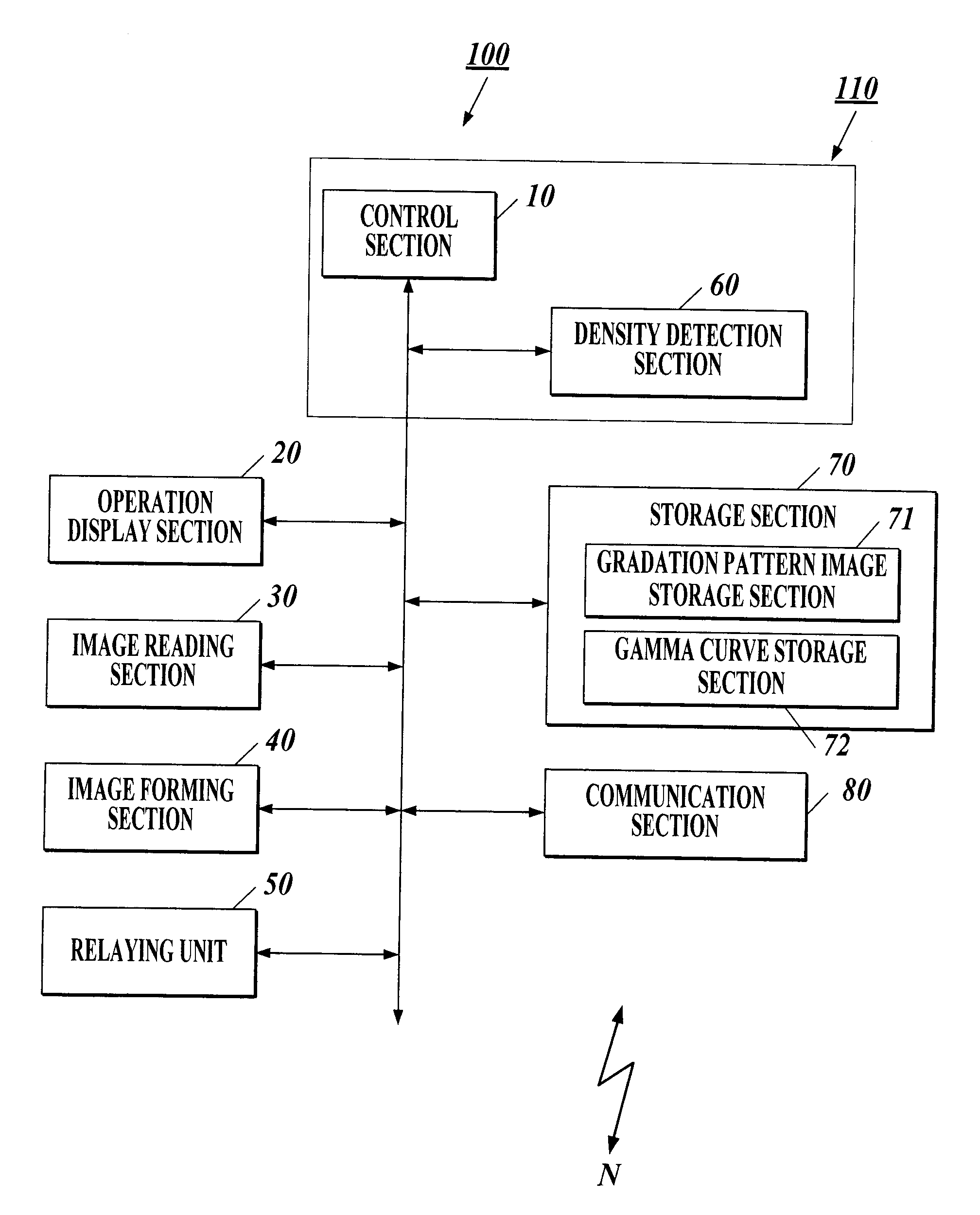
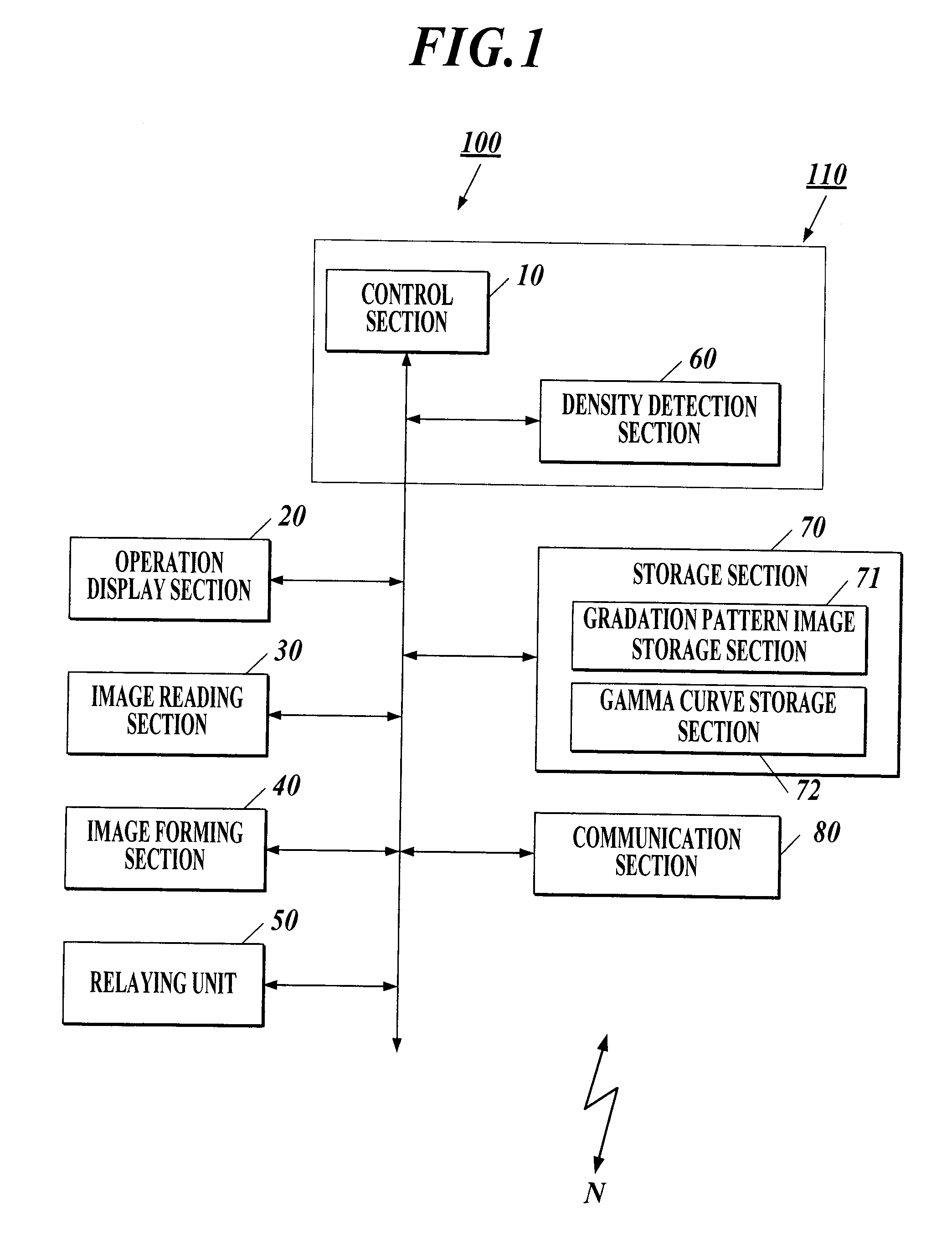
[0059]FIG. 1 shows a functional configuration of an image forming apparatus 100 according to a first embodiment of the present invention. The image forming apparatus 100 is a multifunctional machine having a copying function, an image reading function, a printing function, and the like, and is a color image forming apparatus using an electrophotographic process.
[0060]As shown in FIG. 1, the image forming apparatus 100 includes a control section 10 (density information obtaining section), an operation display section 20, an image reading section 30, an image forming section 40, a relaying unit 50, a density detection section 60 (reflectance detection section), a storage section 70, and a communication section 80. These sections and the like are connected by a bus.
[0061]The control section 10 includes a CPU (Central Processing Unit), a ROM (Read Only Memory), and a RAM (Random Access Memory). The CPU reads a system program or various process programs stored in the ROM in response to o...
example
[0163]By the image forming apparatus 100 according to the embodiment of the present invention, color patches of 1472 colors were outputted and measured, the color patches each of which underwent the gamma correction on the primary, secondary, and tertiary color compositions, and color differences between the measured values and their respective target values were evaluated. As a comparative example, color patches of 1472 colors were outputted and measured, the color patches each of which underwent the gamma correction on only four color compositions of C, M, Y, and K, which is a conventional color adjustment, and color differences between the measured values and their respective target values were evaluated.
[0164]The result thereof is shown in FIG. 18. In the distribution chart shown in FIG. 18, the x axis indicates the color differences between the measured values and their respective target values, the measured values which were obtained by measuring the color patches outputted by...
second embodiment
[0166]Next, a second embodiment of the present invention is described. There are some differences between the density detection section 60 in the second embodiment and the density detection section 60 in the first embodiment. The basic configuration of the image forming apparatus 100 is the same in the first and second embodiments. Therefore, in the second embodiment, the differences from the first embodiment are described, and the components similar to the components described in the first embodiment are denoted by the same reference numerals, and the description thereof is not repeated.
[0167]FIGS. 19A and 19B show a schematic configuration of the density detection section 60 according to the second embodiment. FIG. 19A is an enlarged plan view of the density detection section 60 disposed above the conveyance path C.
[0168]As shown in FIG. 19A, the density detection section 60 includes single-color density sensors 61R, 61G1, 61B, and 61G2 which are arranged parallel to the main-scan...
PUM
 Abstract
Description
Claims
Application Information
 - R&D Engineer
- R&D Manager
- IP Professional
- Industry Leading Data Capabilities
- Powerful AI technology
- Patent DNA Extraction
Browse by: Latest US Patents, China's latest patents, Technical Efficacy Thesaurus, Application Domain, Technology Topic.
© 2024 PatSnap. All rights reserved.Legal|Privacy policy|Modern Slavery Act Transparency Statement|Sitemap