Developing device and image forming apparatus
- Summary
- Abstract
- Description
- Claims
- Application Information
AI Technical Summary
Benefits of technology
Problems solved by technology
Method used
Image
Examples
example 1
[0052]A first example (hereinafter, Example 1) of the developing device 10 to which the present embodiment is applied will be described below.
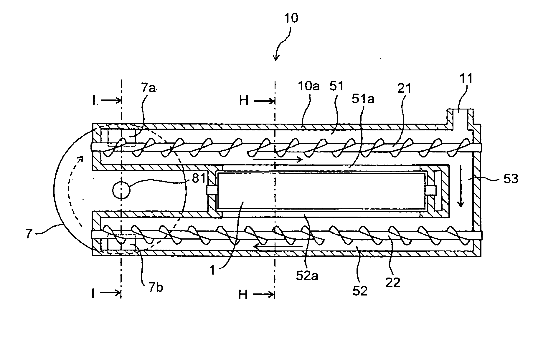
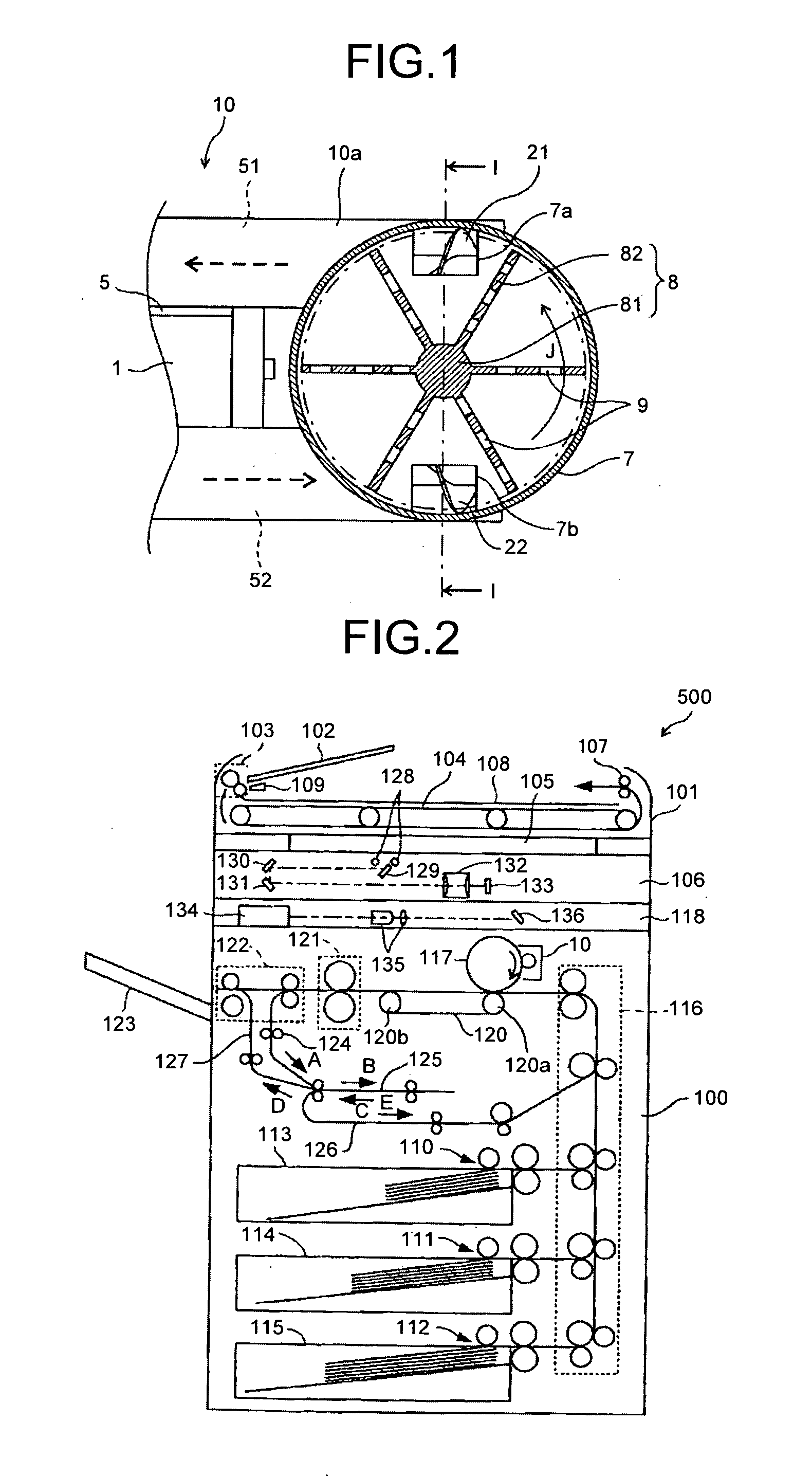
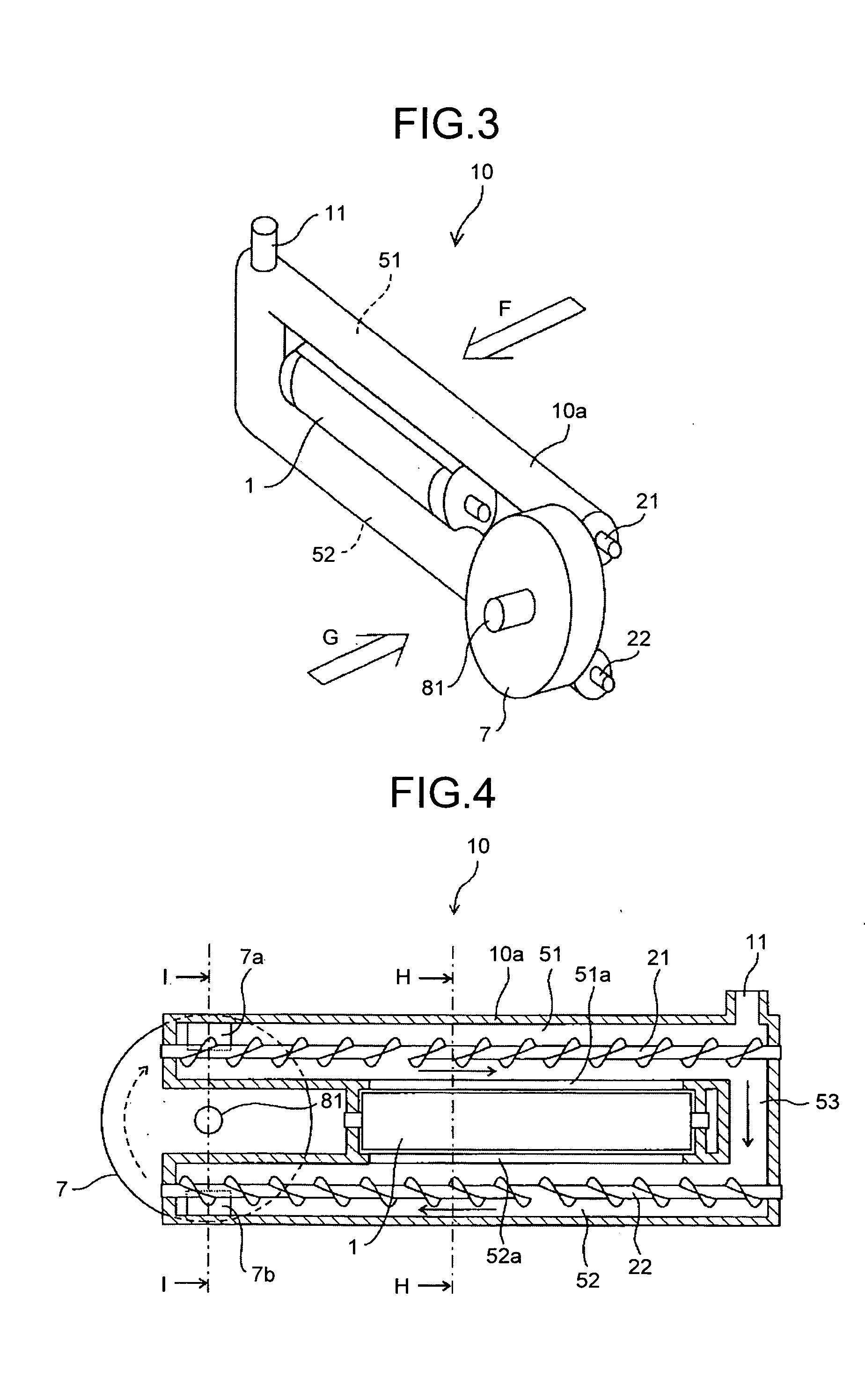
[0053]FIG. 3 is a perspective view of the developing device 10 of Example 1 and FIG. 4 is a cross-sectional view of a developing roller 1 of the developing device 10 and parts near the developing roller 1, viewed from the direction indicated by the arrow F in FIG. 3. FIG. 1 is a cross-sectional view of a developer lifting unit 7 of the developing device 10, viewed in the direction indicated by the arrow G in FIG. 3.
[0054]FIGS. 5A and 5B are cross-sectional views of the developing device 10 taken along the plane orthogonal to the rotation axis of the developing roller 1. FIG. 5A is a cross-sectional view of the developing device 10 taken along the line H-H in FIG. 4 in a position where the developing roller 1 is arranged; and FIG. 5B is a cross-sectional view of the developing device 10 taken along the line I-I in FIG. 1 and FIG. 4 in a positio...
example 2
[0107]A second example (hereinafter, “Example 2”) of the developing device 10 to which the present embodiment is applied will be described below.
[0108]FIG. 9 is a perspective view of the developing device 10 of Example 2; and FIG. 10 is a cross-sectional view of the developer lifting unit 7 of the developing device 10 and parts near the developer lifting unit 7, viewed from the direction indicated by the arrow M in FIG. 9.
[0109]FIG. 11 is a cross-sectional view of the developer lifting unit 7 taken along the line T-T in FIG. 10 that is the plane orthogonal to the rotation axis of the developing roller 1.
[0110]The developing device 10 of Example 2 has a configuration in which a center position 2 configured such that the center position of the rotating paddle 8 in the axial direction approximately coincides with the position of a virtual plane a connecting the rotation shafts of the two screw members. The mechanism for circulating the developer is the same as that in Example 1.
[0111]I...
example 3
[0113]A third example (hereinafter, “Example 3”) of the developing device 10 to which the present embodiment is applied will be described below.
[0114]FIG. 12 is a perspective view of the developing device 10 of Example 3; and FIGS. 13A and 13B are cross-sectional views of the developing device 10 of Example 3 in FIG. 12. FIG. 13A is a cross-sectional view of the developing device 10 taken along a plane Q in FIG. 12; and FIG. 13B is a cross-sectional view of the developing device 10 taken along a plane R in FIG. 12.
[0115]The developing device 10 of Example 3 has the supplying-collecting integration system in which a circulating-conveying path 252 is positioned below the supplying-conveying path 51 and the supplying screw 21 and the collecting screw 22 are arranged in parallel with the developing roller 1.
[0116]In the developing device 10 of Example 3, the supplying screw 21 is arranged to be lower than and oblique to the developing roller 1 and a circulating screw 222 is arranged ver...
PUM
 Abstract
Description
Claims
Application Information
 - R&D
- Intellectual Property
- Life Sciences
- Materials
- Tech Scout
- Unparalleled Data Quality
- Higher Quality Content
- 60% Fewer Hallucinations
Browse by: Latest US Patents, China's latest patents, Technical Efficacy Thesaurus, Application Domain, Technology Topic, Popular Technical Reports.
© 2025 PatSnap. All rights reserved.Legal|Privacy policy|Modern Slavery Act Transparency Statement|Sitemap|About US| Contact US: help@patsnap.com


