Electrical connector with high intensity contacts

Inactive Publication Date: 2012-03-01
HON HAI PRECISION IND CO LTD
View PDF0 Cites 10 Cited by
  • Summary
  • Abstract
  • Description
  • Claims
  • Application Information

AI Technical Summary

Benefits of technology

[0006]An object of the invention is to provide an electrical connector w

Problems solved by technology

The pressing force is also exerted on the elastic port

Method used


Image

  • Electrical connector with high intensity contacts
  • Electrical connector with high intensity contacts
  • Electrical connector with high intensity contacts

Examples


Example

[0013]Reference will now be made in detail to the preferred embodiment of the present invention.

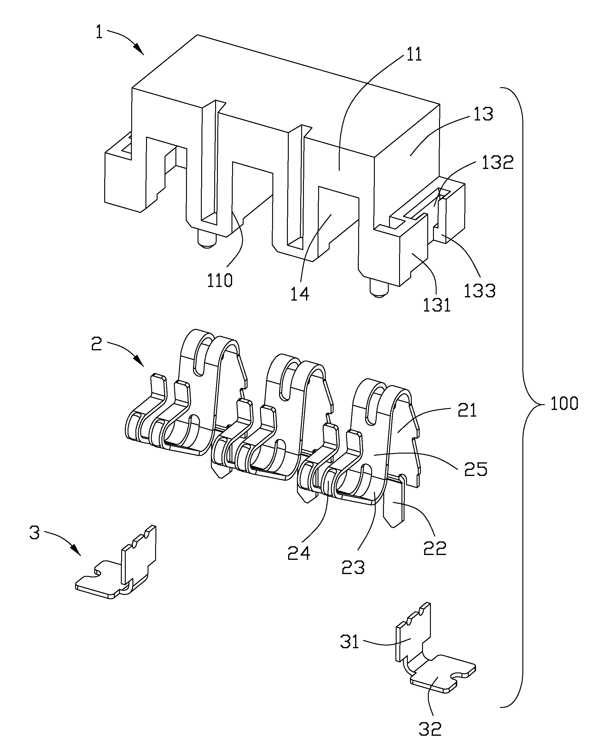
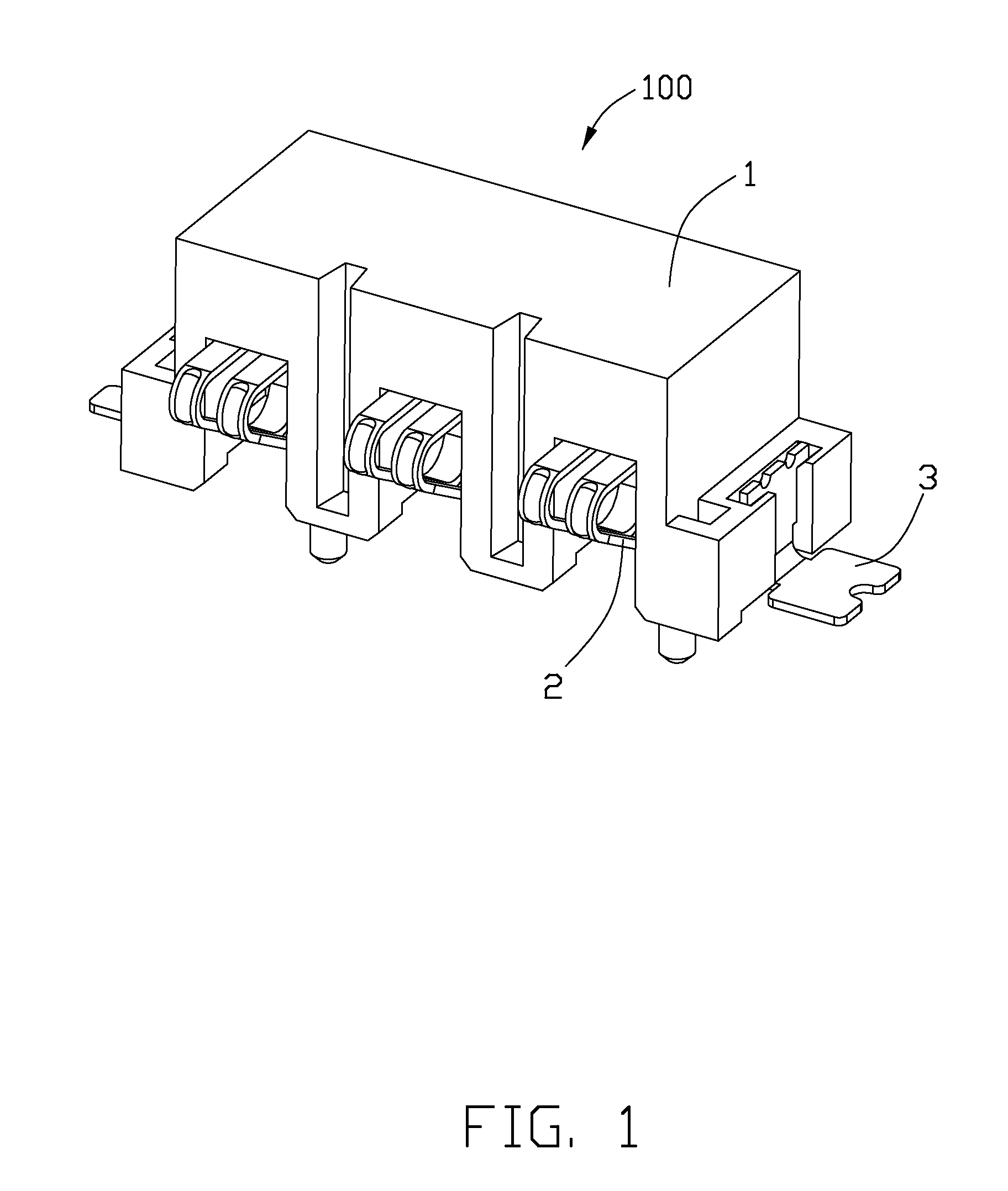
[0014]Referring to FIGS. 1, an electrical connector 1 in accordance with an embodiment of the present invention is a battery connector. The connector 100 comprises a rectangle insulative housing 1, a plurality of elastic contacts 2 secured in the insulative housing 1 and a pair of soldering pads 3 disposed at two sides of the insulative housing 1.

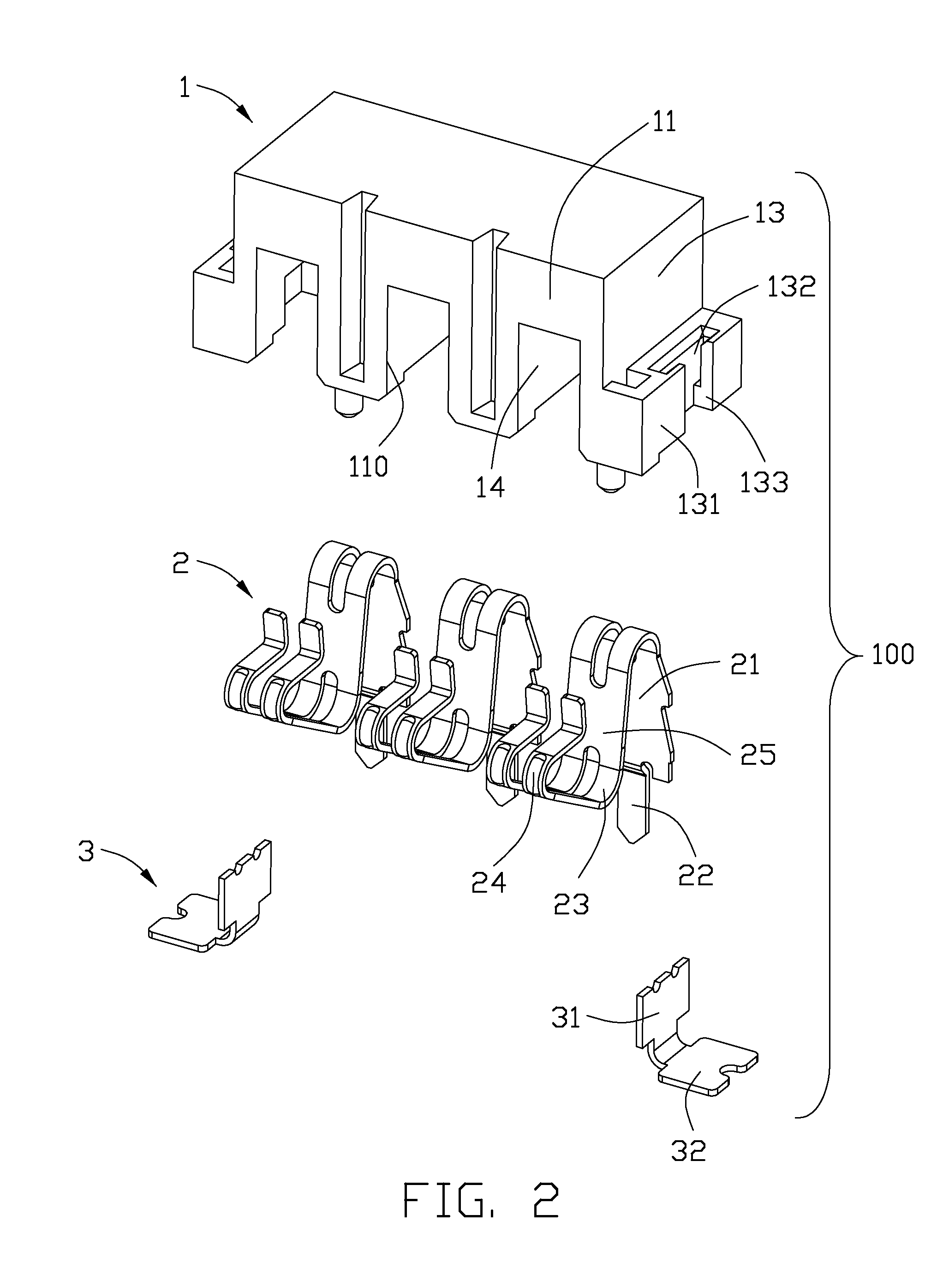
[0015]Referring to FIGS. 2 and 3, the insulative housing 1 defines a mating surface 11 intended for confronting with a complementary connector (not shown), a mounting surface 12 perpendicular to the mating surface 11 and two side surfaces 13 connecting with the mating surface 11 and the mounting surface 12. A plurality of passageway 14 running through the mating surface 11 and the mounting surface 12. Each passageway 14 has a front opening 110 formed at the mating surface 11 and a bottom opening 120 formed at the mounting surface 12. The contacts...


PUM


Abstract

An electrical connector includes an insulative housing defining a mating surface, a mounting surface and a plurality of passageways running through the mating surface and the mounting surface and a plurality of contacts upwardly assembled into the corresponding passageways. Each of the contacts defines an upright retention portion interfered with the passageway, a pair of elastic arms extending from the retention portion and spaced apart with each other and a lying V-shaped contacting portion formed by a distal end of each elastic arms bending and extending beyond the mating surface of the housing. Each contact defines a connecting portion connecting with the pair of elastic arms and received in the passageway.

Description

BACKGROUND OF THE INVENTION[0001]1. Field of the Invention[0002]The present invention generally relates to an electrical connector, and more particularly, to a novel structure of an electrical connector with contacts prevented from deformation.[0003]2. Description of Related Art[0004]An electrical connector includes an insulative housing and a plurality of contacts upwardly secured into passageways of the insulative housing. Each contact defines a retention portion interfered with the passageway, a contacting portion protruding from a mating face of the insulative housing and an elastic portion receiving in the receiving passageway and connecting with the contacting portion and the retention portion. In a process of the electrical connector mating with a complementary connector, a lateral pressing force is exerted on the contacting portions to result the contacting portions moving to the mating face. The pressing force is also exerted on the elastic portions to result in deformation...

Claims


Application Information

Patent Timeline
IPC IPC(8): H01R24/00
CPCH01R12/716H01R13/41H01R13/2457
Inventor ZHU, YU
Owner HON HAI PRECISION IND CO LTD
Why Eureka
Try Eureka