Anti-Refluxive and Trigone Sparing Internal Ureteral Stent

a ureteral stent and anti-reflux technology, applied in the field of internal ureteral stents, can solve the problems of threatening renal function, ureteral stents, and may produce adverse effects, and achieve the effect of reducing reflux and/or eliminating reflux and improving the comfort of the device for patients

Active Publication Date: 2012-03-01
RICKNER THOMAS W
View PDF25 Cites 43 Cited by
  • Summary
  • Abstract
  • Description
  • Claims
  • Application Information

AI Technical Summary

Benefits of technology

[0009]In one embodiment of the present invention, the elongated body has an upper, tubular body that is connected to the coiled, renal segment and a lower, intramural segment that is connected to the coiled, bladder end segment such that the lower, intramural segment and coiled, bladder end segment are provided as a first flap and a second flap. The lower, intramural segment is of such length as to extend through a patient's intramural ureter, preferably 2-4 cm. One benefit of this configuration is the reduction and / or elimination of reflux of a patient's urine back into the ureter through the stent towards the kidneys.
[0010]In another embodiment of the present invention, the coiled, renal segment is provided in a first plane and the coiled, bladder end segment is provided in a second plane such that the first plane and the second plane are transverse with respect to one another. One benefit of this configuration is that the coiled, bladder end segment is positioned away from a patient's trigone which improves the comfort of the device to the patient.

Problems solved by technology

Serious obstructions may cause urine to back up into the kidneys, threatening renal function.
Ureteral stents, particularly the portion positioned in the ureter near the bladder and inside the bladder, may produce adverse effects including blood in the urine, a continual urge to urinate, and flank pain accompanying reflux of urine up the stent (e.g. when voiding) as pressure within the bladder is transmitted to the kidney.
In short, stents may cause or contribute to significant patient discomfort and serious medical problems.

Method used


Image

  • Anti-Refluxive and Trigone Sparing Internal Ureteral Stent
  • Anti-Refluxive and Trigone Sparing Internal Ureteral Stent
  • Anti-Refluxive and Trigone Sparing Internal Ureteral Stent

Examples


Embodiment Construction

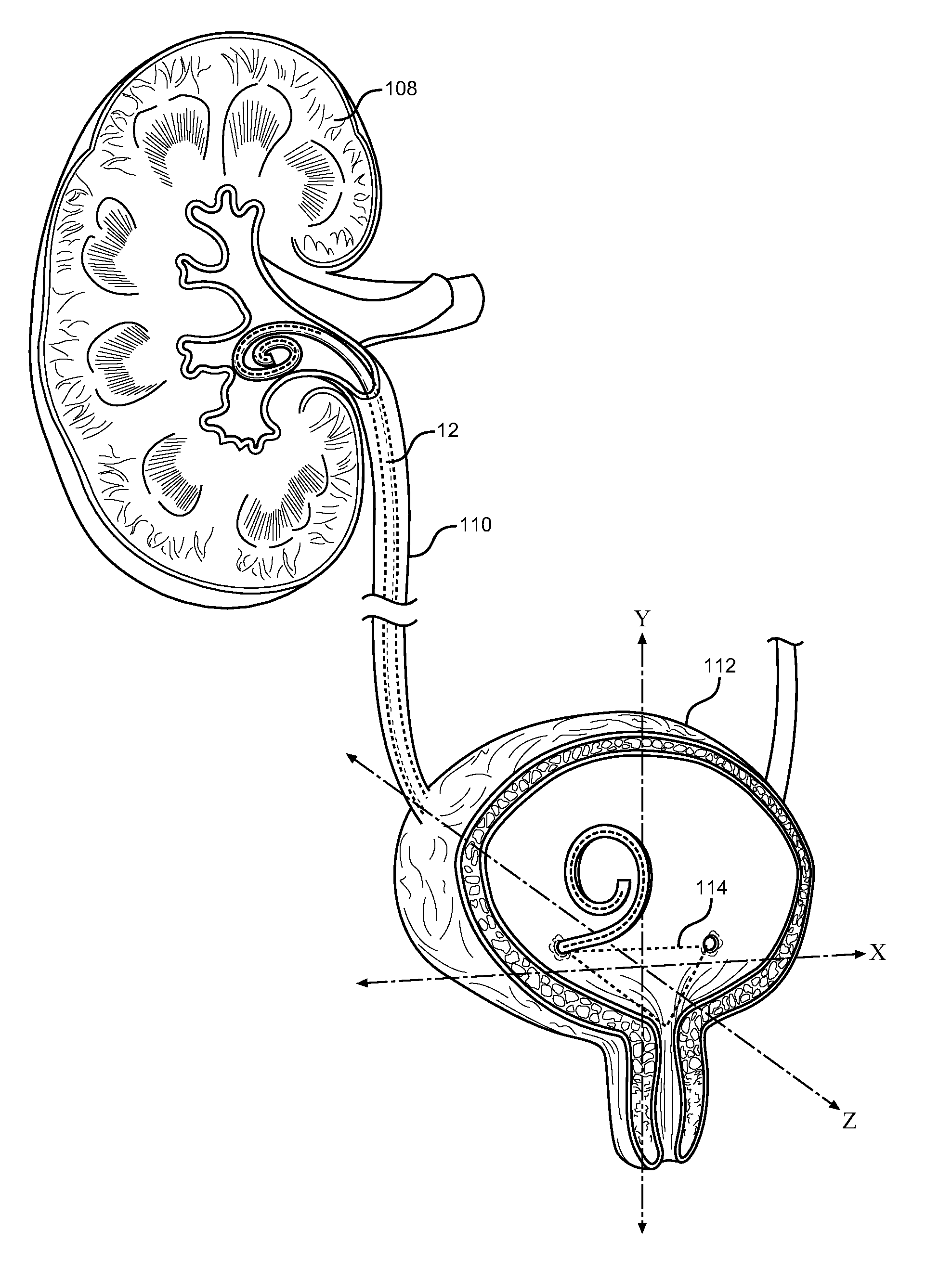
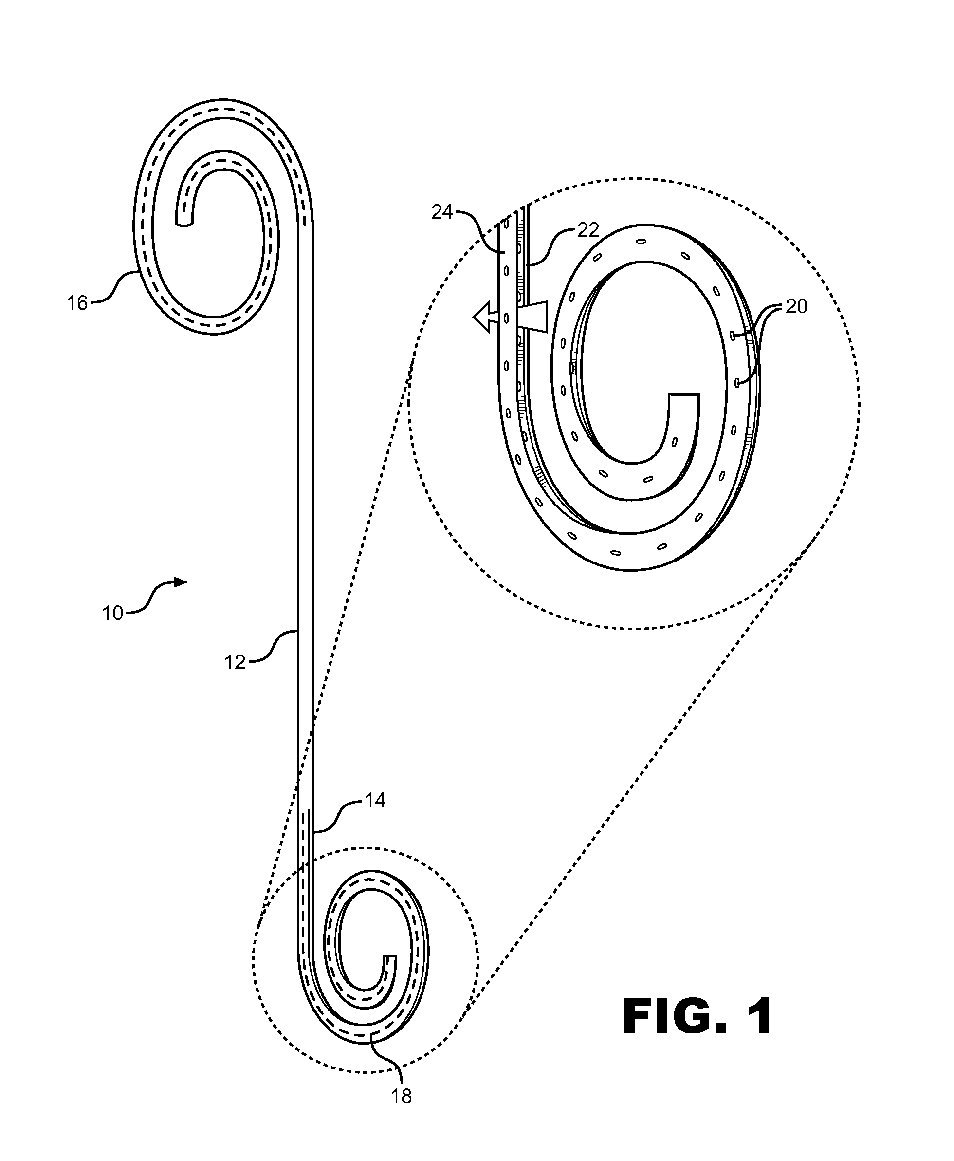
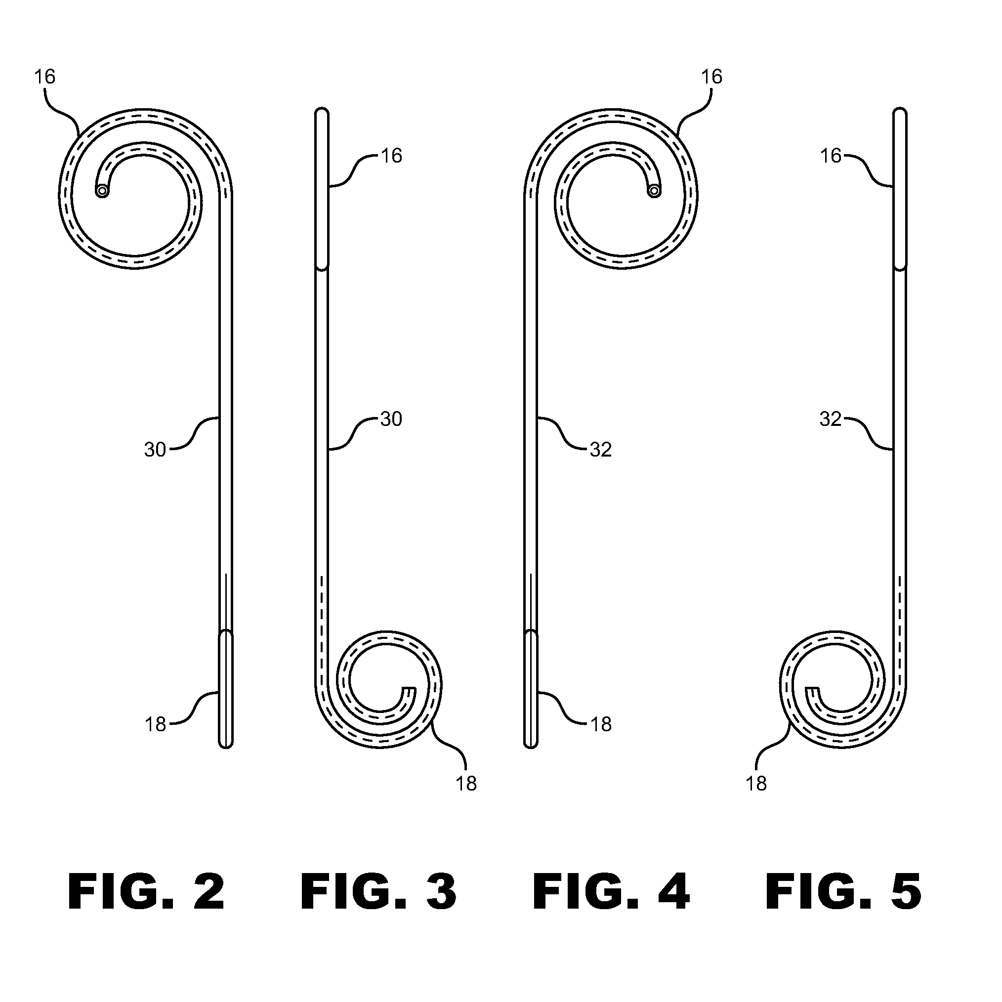
[0023]FIG. 1 shows a ureteral stent 10 including an elongated body having a proximal end connected to a coiled, renal segment 16 and a distal end connected to a coiled, bladder end segment 18. The elongated body is designed to extend from the renal pelvis to the ureteral orifice. In a preferred embodiment, the elongated body has an upper, tubular body 12 that is connected to the coiled, renal segment at its proximal end and a lower, intramural segment 14 at its distal end that extends through the intramural ureter and connects to the coiled, bladder end segment 18. The upper, tubular body 12 has annular walls having an inner and outer diameter. The outer diameter of the upper, tubular body 12 may be substantially uniform throughout much of the length of the tube, or it may taper from a relatively short region of larger diameter (e.g. the site of repair, where there is a risk that the healing process will substantially restrict flow in the lumen) to a region of generally small diamet...


PUM


Abstract

A ureteral stent has an elongated body connecting a coiled, renal segment to a coiled, bladder end segment. In one embodiment of the present invention, the coiled, bladder end segment and a lower, intramural segment of the elongated body are provided as a first flap and a second flap. The lower, intramural segment is of such length as to extend through a patient's intramural ureteral, preferably 2-4 cm. In another embodiment of the present invention, the coiled, renal segment is provided in a first plane and the coiled, bladder end segment is provided in a second plane such that the first plane and the second plane are transverse with respect to one another.

Description

BACKGROUND OF THE INVENTION[0001]1. Field of the Invention[0002]The present invention relates to internal ureteral stents.[0003]2. Description of Related Art[0004]Internal ureteral stents are generally used to assist movement of urine along a patient's ureter and into the patient's bladder in patients with ureteral obstructions or injury, or to protect the integrity of the ureter in a variety of surgical manipulations. Ureteral stents may be used to treat or avoid ureteral obstructions, such as ureteral stones or ureteral tumors, which disrupt the flow of urine from the kidneys to the bladder. Serious obstructions may cause urine to back up into the kidneys, threatening renal function.[0005]Generally, ureteral stents are formed from a flexible material having sufficient resiliency to allow it to be straightened for insertion into the body passageway, while having sufficient memory to return to its predetermined retentive shape when in situ. Ureteral stents are positioned in the uret...

Claims


Application Information

Patent Timeline
Patent Type & Authority Applications(United States)
IPC IPC(8): A61F2/04
CPCA61M27/008
Inventor RICKNER, THOMAS W.
Owner RICKNER THOMAS W
Why Eureka
Try Eureka