Keypad lockset

a keypad lock and keypad technology, applied in the field of electronic door locks, can solve the problems of preventing customers from upgrading their traditional mechanical locks to digital keypad locks, affecting the aesthetic appeal of locks, and affecting the quality of locks, etc., to achieve accurate and reliable engagement, enhance geometry, and ensure the effect of positioning

Active Publication Date: 2012-03-08
ASSA ABLOY RESIDENTIAL GRP INC
View PDF3 Cites 25 Cited by
  • Summary
  • Abstract
  • Description
  • Claims
  • Application Information

AI Technical Summary

Benefits of technology

[0012]The locks described herein provide both relatively low profile cosmetic and functional traits while preserving the ability to use standard lock cylinders and door preparation.
[0015]The preferred clutch mechanism used in the lever embodiment is adapted to engage and disengage the connection between the input axis and the output axis. A cantilever wire spring mechanism provides for engagement through the activation of the motor that drives a preferably square piston pin. The alignment of one side of the clutch to the other side of the clutch is provided by springs that bias the clutch components in their home positions so that they are accurately and precisely positioned for smooth engagement of the piston pin with the transfer hub pocket upon actuation. The preferred present clutch transfer hub system permits accurate and reliable engagement.
[0016]In the preferred lever embodiment clutch mechanism, a piston pin with a square or rectangular cross section, which is driven by a motor, is pushed into the clutch transfer hub to engage the connection of the motion. Furthermore, for lever lock type locks that have a pre-defined initial position, the mating recess in the transfer hub to which the piston pin engages has an enhanced geometry, that is, a geometry that allows for a slight angular offset of + / −4 degrees that permits engagement but with some allowance for misalignment. The preferred transfer hub has a diagonal interface engagement with the piston pin instead of an edge-to-edge face interface. A further enhancement is the use of the pin with a rectangular cross section which will allow only a single defined relationship for the engagement when considered against the range of rotation possible with the lever input. This technique prevents a false relationship of engagement that could occur with a square or other polygon where the clutch could couple the lever to the latch at the end of the lever stroke which would not allow the latch to then operate as expected and could damage the lock.

Problems solved by technology

However, many of the locks currently in the market are too large to fit with storm doors or are too bulky to provide good aesthetic appeal.
A further barrier to customer acceptance occurs in designs that require additional holes to be drilled into a door in addition to the standard residential bored door prep.
These deficiencies deter customers from upgrading their traditional mechanical locks to digital keypad locks.
Additional problems associated with electronic locks derive from different and conflicting goals for various parts of the lock.
For example, the height of a keypad lock cannot be so high that it can no longer fit the space between the main door and the storm door.
The conflict is also related to the relatively long length of standard key cylinders in relation to a typically desired low profile lock thickness or height.
Non-synchronization in any one of the moving parts may cause the lock to not function as intended.
When the levers sag or otherwise are out of adjustment, the transmission will cause the clutch elements to become misaligned.
In this case when a valid code is presented to the controller and the electromechanical clutch is commanded to engage, the latch will fail to respond to the turning of the lever because the clutching elements were not in alignment and ready to receive their respective engaging surfaces.
This problem can hinder the locking and unlocking functions, as well as cause security and safety concerns for users.

Method used


Image

  • Keypad lockset
  • Keypad lockset
  • Keypad lockset

Examples


Embodiment Construction

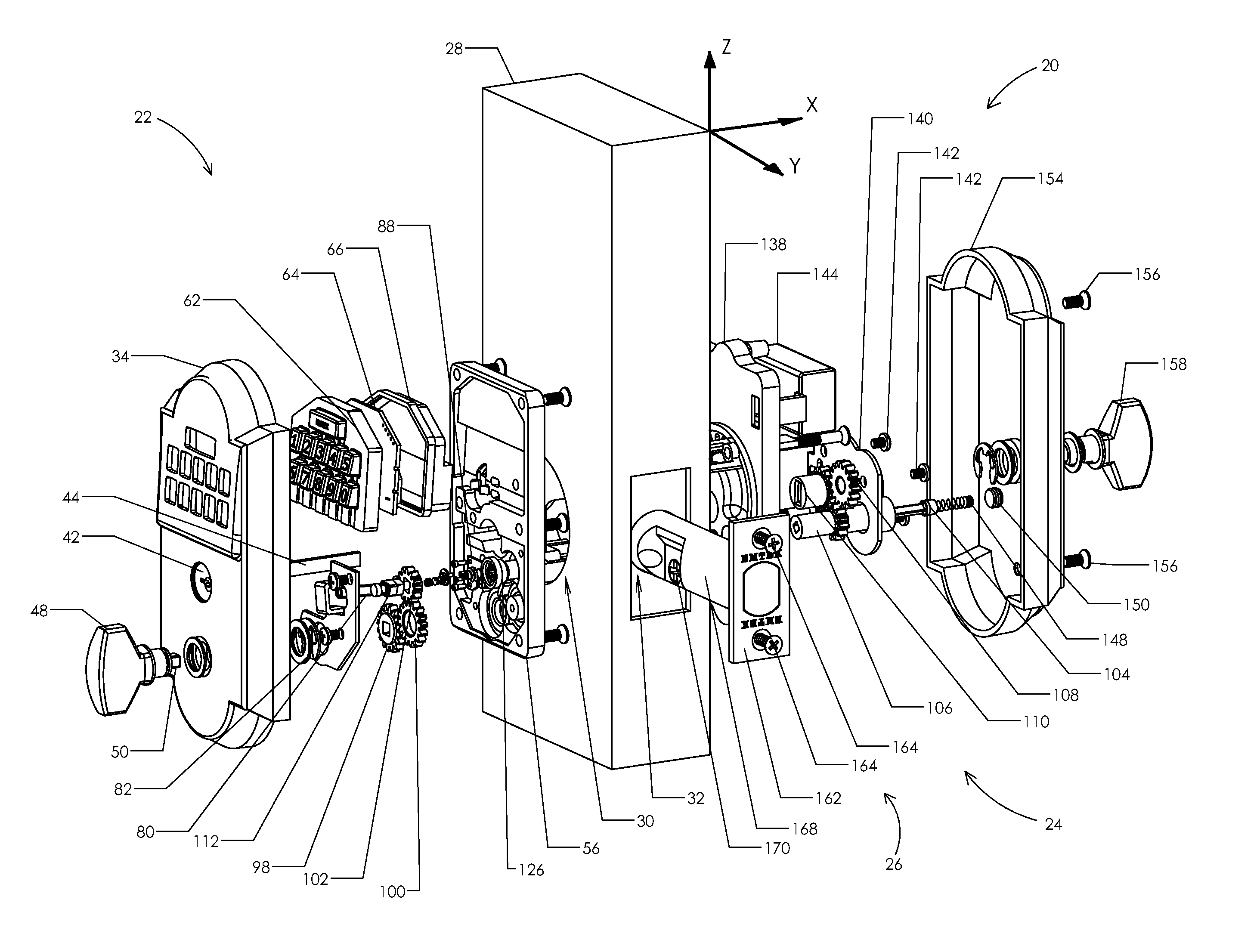
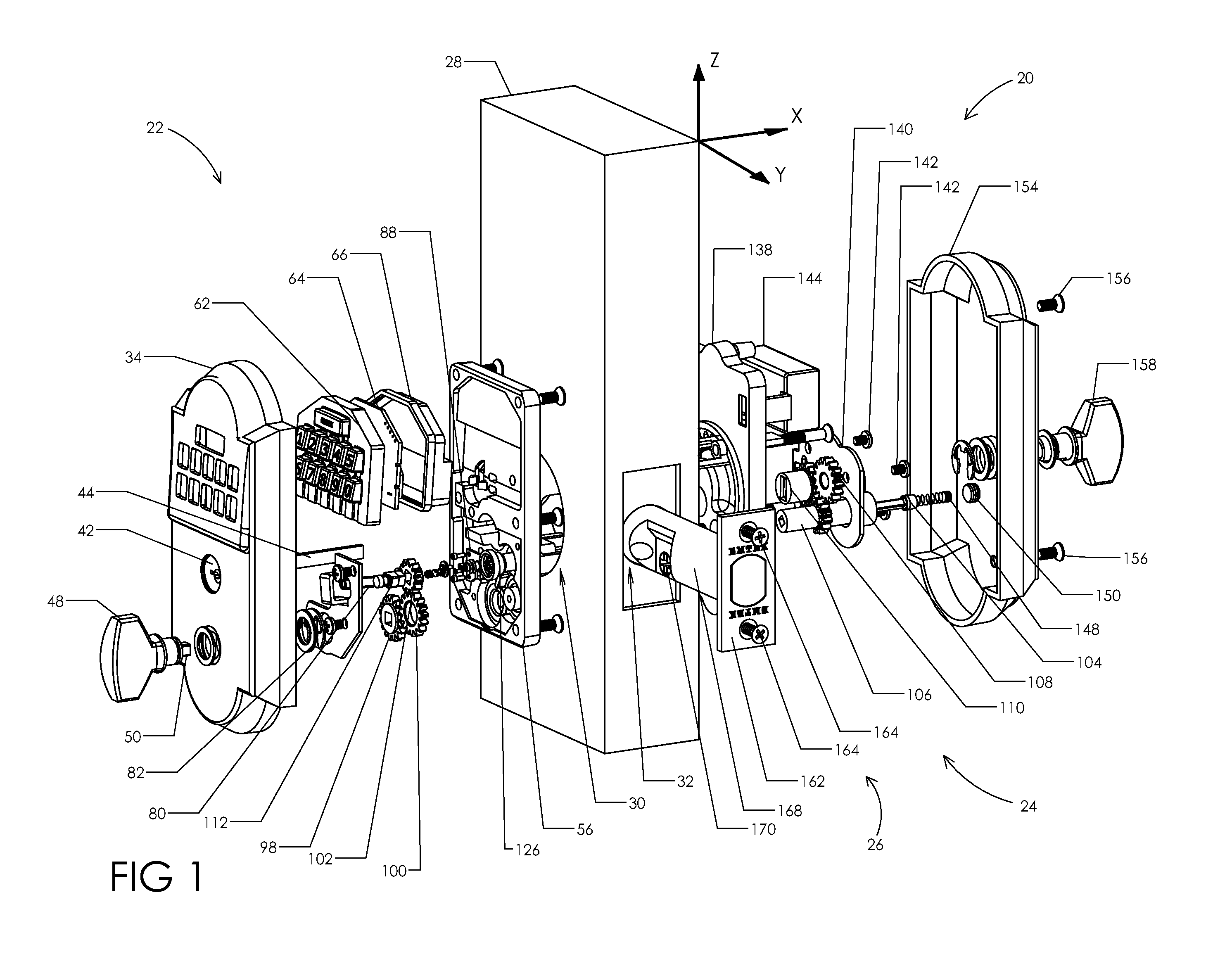
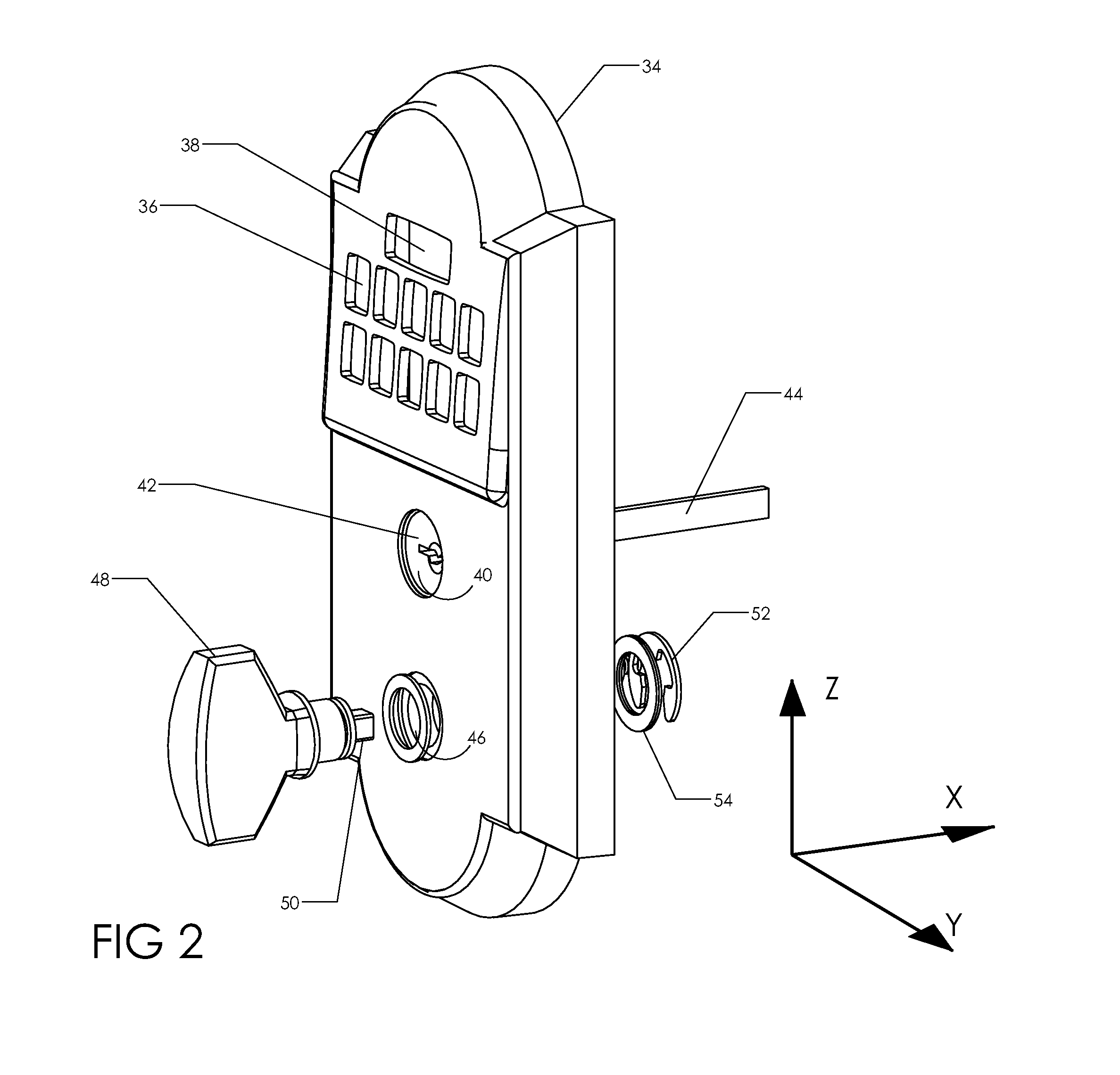
[0055]For convenience in describing the components, sub-assemblies, the fully assembled keypad lockset embodiments and their spatial and functional relationships, each to the other, the terms vertical or height as used herein refers to the direction from the bottom to the top, or vice versa of a door as it is normally found installed in a building, that is, along the z axis as shown in various figures. The term depth refers to the direction from the outside to the inside, or vice versa of a door as it is normally found installed in a building, that is, along the x axis as shown in various figures. The term width refers to the direction from left to right, or vice versa as a person is facing a door is it is normally found installed and shut in a building, that is, along the y axis as shown in various figures. The terms exterior, outside or external refer to the side of the door on which the keypad is positioned, and the terms interior, internal, inside or inner refer to the other sid...


PUM


Abstract

A keypad lockset adapted for deadbolt as well as lever locks, and having as a first embodiment an exterior gear train, an interior gear train, and an electronically controlled clutch for coupling the gear trains when engaged and for uncoupling the gear trains when the clutch is disengaged, so that when the clutch is engaged rotation of an external thumb turn will permit the door latch to be withdrawn and thus to permit opening of the door, and a mechanical override mechanism that can be operated in case of electrical failure, and in which clutch mechanism and the override mechanism both operate through the single, standard 2 and ⅛ inch door preparation hole, or alternatively as a second embodiment, a keypad lockset in which two four-bar mechanical linkages are used in place of gears as means to actuate the clutch, and alternatively to provide for a pass-through override function.

Description

CROSS REFERENCE TO RELATED APPLICATION[0001]This application is a utility patent application based on, incorporates by reference and claims the benefit of priority of U.S. provisional patent application 61 / 168,558, filed Apr. 10, 2009, and U.S. provisional patent application 61 / 185,184, filed Jun. 8, 2009, both of which are incorporated by reference.FIELD OF INVENTION[0002]The invention relates generally to electromechanical door locks, and more particularly to electromechanical door locks having an electronically controlled clutch mechanism and a mechanical override mechanism.BACKGROUND OF INVENTION[0003]Keypad locks are becoming widely accepted in the residential market. However, many of the locks currently in the market are too large to fit with storm doors or are too bulky to provide good aesthetic appeal. A further barrier to customer acceptance occurs in designs that require additional holes to be drilled into a door in addition to the standard residential bored door prep. The...

Claims


Application Information

Patent Timeline
Patent Type & Authority Applications(United States)
IPC IPC(8): E05B47/00
CPCE05B17/042E05B47/0012E05B47/068E05B2047/0086E05B2047/002E05B2047/0031E05B2015/0496Y10T292/096Y10T70/7102Y10T292/102Y10T70/7107Y10T70/5681Y10T292/1015Y10T70/7062Y10T70/7119Y10T70/7068Y10T292/0977Y10T70/7124Y10T70/5398Y10T70/7113Y10T70/5416Y10T70/713Y10T70/5155
Inventor SORENSEN, BIRK CLIFFTSAI, PING HSIENWONG, WAI PANGWALSH, JOHN EDWARDMARTINEZ, LOULS ROMO
Owner ASSA ABLOY RESIDENTIAL GRP INC
Why Eureka
Try Eureka