
Power generating device

a power generation device and power technology, applied in the direction of dynamo-electric machines, light sources, lighting apparatuses, etc., can solve the problems of easy leakage of batteries, poor user experience, and easy traffic accidents, so as to increase the traffic safety of users, easy to fit in shoes, and increase the recognition of users

Active Publication Date: 2012-03-08
TSENG SHEN KO
View PDF6 Cites 7 Cited by
  • Summary
  • Abstract
  • Description
  • Claims
  • Application Information

AI Technical Summary

Benefits of technology

[0007]One scope of the present invention is to provide a power generating device, which can utilize a simple action of people to generate electrical energy, do not need to have the mercury battery with high pollution, generate a LED source, and increase the traffic safety for people.
[0011]In summary, the power generating device of the present invention is able to have the application in shoe-pads, ground mats or any other suitable device, while the user steps or presses the power generating device. The power generating device utilizes the electromagnetic induction to generate the induced current and further saves the said the induced current for supplying to LED. Therefore, the power generating device of the present invention is able to be configured in the shoes easily and generates the electrical energy automatically in the process of walking. More particularly, the lighting module of the power generating device of the present invention is able to increase the recognition for the user in the evening, so as to increase the traffic safety for the user.

Problems solved by technology

On the other hand, when the pedestrians walk at night, if the surrounding ambient light is weak, the traffic accidents are very easily taken place.
However, the thin battery containing the mercury always leads to pollute the environment.
In addition, if the above fittings do not have good waterproof equipments, the battery is easily leakage, damp or damaged.

Method used


Image

  • Power generating device
  • Power generating device
  • Power generating device

Examples


Embodiment Construction

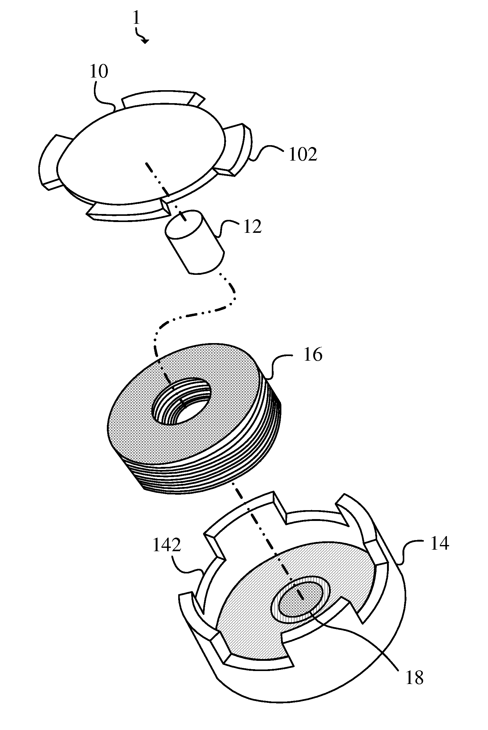
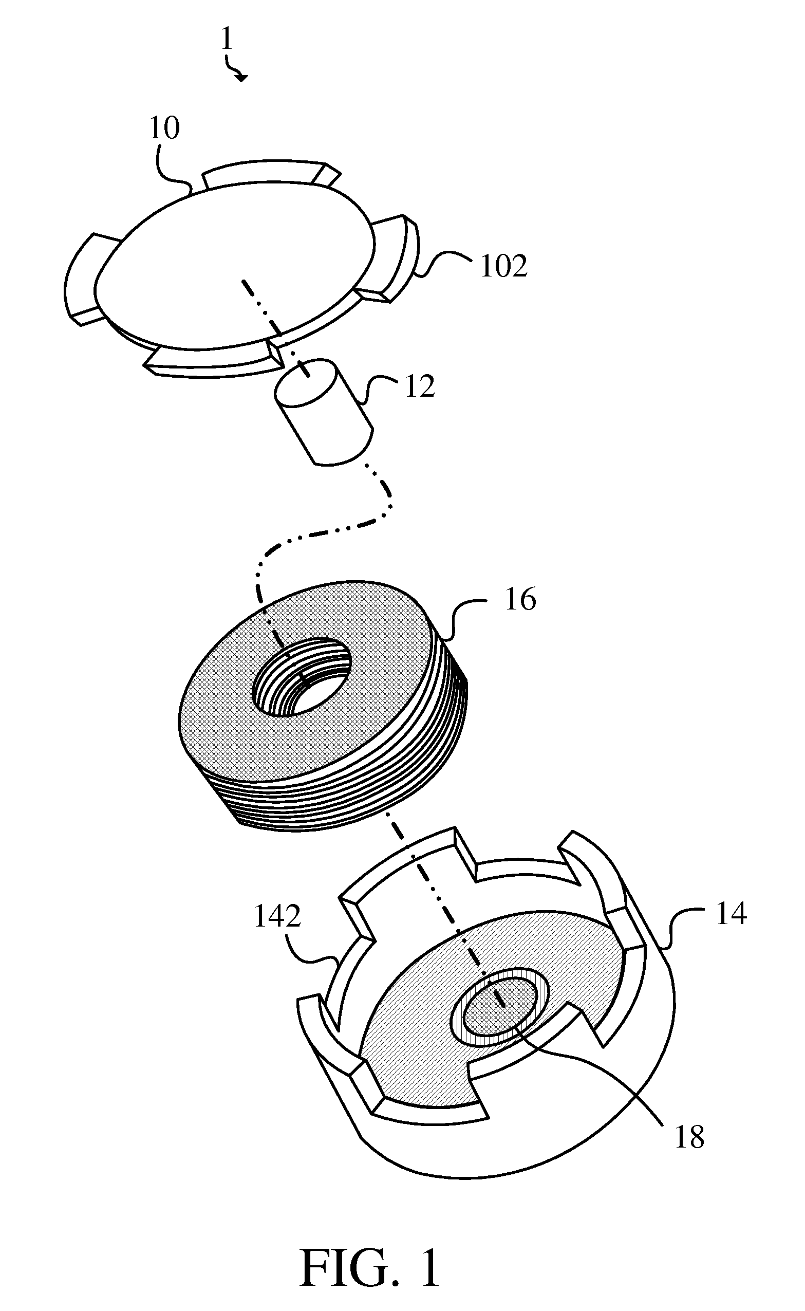
[0020]Please refer to FIG. 1, FIG. 1 is an exploded view of the power generating device of one embodiment of the present invention. As shown in FIG. 1, the power generating device 1 comprises a first shell 10, a magnetic unit 12, a second shell 14 and a inductance coil 16. Moreover, the first shell 10 and the second shell 14 are able to engage to each other so as to form a space, the magnetic unit 12 and the inductance coil 16 are configured in the said space. For more detailed description of the above components and the functions thereof, please read the followings.

[0021]The first shell 10 comprises at least a first engaging part 102. In actual practice, the first engaging part 102 can be a component disposed on the first shell. Besides, the first engaging part 102 can also be formed with the first shell 10 in one body. Moreover, the first engaging part 102 is not limited to a fan-shaped component, the first engaging part 102 is able to be any other suitable shape.

[0022]The magneti...


PUM


Abstract

The invention discloses a power generating device comprising a first shell, a magnetic unit, a second shell and an inductance coil. The first shell comprises at least a first engaging part. The magnetic unit is disposed on the first shell. The second shell comprises at least a second engaging part which is detachably engaged to the first engaging part making the first shell and the second shell form a space, wherein the magnetic unit is disposed inside the space. The inductance coil is disposed on the second shell inside the space, and the magnetic unit is surrounded by the inductance coil. When an external force is applied to the first shell and the second shell, the first engaging part moves relatively to second engaging part, and the inductance coil generates an induced current by sensing changes of a magnetic flux.

Description

BACKGROUND OF THE INVENTION[0001]1. Field of the Invention[0002]The present invention is related to a power generating device, more particularly, the present invention is related to a power generating device utilizing the electromagnetic induction to generate electrical energy.[0003]2. Description of the Prior Art[0004]In order to promote green energy with current world trend, there were many products with both practicability and energy-efficiency on the market. The commodity of utilizing simple actions of people for generating electrical energy can not only achieve the effect of energy saving, but also have a memorable fun in use. For example, the flashlight with generating electrical energy by hand and the bicycle with changing mechanical energy into electrical energy are the practical products with the function of generating electricity.[0005]On the other hand, when the pedestrians walk at night, if the surrounding ambient light is weak, the traffic accidents are very easily take...

Claims


Application Information

Patent Timeline
Patent Type & Authority Applications(United States)
IPC IPC(8): H05B37/02H02K35/06
CPCH02K35/04H02K35/02
Inventor TSENG, SHEN-KOLIAO, JUINNE-CHING
Owner TSENG SHEN KO
Features
  • Generate Ideas
  • Intellectual Property
  • Life Sciences
  • Materials
  • Tech Scout
  • Unparalleled Data Quality
  • Higher Quality Content
  • 60% Fewer Hallucinations
Learn More